This thread has been locked.

If you have a related question, please click the "Ask a related question" button in the top right corner. The newly created question will be automatically linked to this question.

TM4C123 slave write after repeated start issue

Other Parts Discussed in Thread: EK-TM4C123GXL

Picture.xlsx1. customer issue describe

Here is one issue that customer found when another MCU use I2C master write read with repeated start condition to TI chip.

The test program in TI chip only initialize GPIO pin 2, 3 as I2C function and act as slave.

The interrupt handler is very simple.

I2C handler read all master request package data when interrupt rise I2C_SLAVE_ACT_RREQ_FBR and I2C_SLAVE_ACT_RREQ status flag without any process action.

-        Only “i2cDate = I2CSlaveDataGet(I2C0_SLAVE_BASE)”

And write back 0xF0 constant value when interrupt rise I2C_SLAVE_ACT_TREQ status flag. (depend on master read number)

-        I2CSlaveDataPut(I2C0_SLAVE_BASE, 0xF0);

From the TI driverlib “TivaWare_C_Series-2.1.3.156” seems it direct write to I2CSDR register in hardware I2C controller.

But, the actually result measure from oscilloscope seems always fail in first four bytes value after response slave address to master.

And they also didn’t see any explain about slave read after repeated start condition in “Datasheet”.

Interrupt handler:

cid:image007.jpg@01D23E65.E5967EB0

Customer did a simple test: after repeated start, slave always write 0xF0

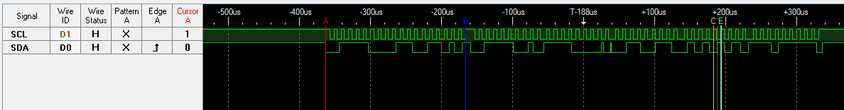
The test waveform is Fig1 and Fig2(Fig2 is a continuation of Fig1)

Red(marked 1) – response slave address

Orange(marked 2) – slave write 0xF0(sometimes will be error)

Purple(marked 3,4,5) – slave write 0x00(should be 0xF0, they are error)

Green(marked 6,7) – slave write 0xF0(they are right, from marked 6, slave write will always right)


Fig1

Fig2

Please find the picture as attached. thanks!

2. Support need:

Master->Slave(TI TM4C123), please help to do the test with the below sequence

  • Master write to slave

  • repeat start read data from slave

  • read byte >5 byte

if all read byte is correct, please kindly provide your code to us, and I will ask customer do the test with your code.

If you can emersion the customer issue, please kindly give your comment.

Thanks a lot!

  • Hello Alex

    There is no image attached in your original post. Also we would like to see how the slave code has been structured in the customer code so that we an analyze it against the waveform.
  • Hello Alex,

    I checked the XLSX file as well. My first observation is that the interrupt clear mechanism is trying to clear TREQ, FBR and RREQ bits of the I2C Slave Status register. Please note that this are RO bits and are not related to the Interrupt Status for the slave.
  • Hi Alex,

    Thanks for your help to post this topic.

    Hi Ashara,

    To clear those bits is just because we already try not to clear those bit and the result is the same.
    It always response fixed error data in first four bytes.
    Case 1:
    I2CSlaveDataPut(I2C0_SLAVE_BASE, 0xF0) => It will response "0xF0 0x00 0x00 0xE0" in first four bytes.
    Case 2:
    I2CSlaveDataPut(I2C0_SLAVE_BASE, 0xA1) => It will response "0xA1 0x00 0x00 0xA1" in first four bytes.
    Case 3:
    I2CSlaveDataPut(I2C0_SLAVE_BASE, 0x55) => It will response "0x51 0x00 0x00 0x45" in first four bytes.

    Is there any other suggestion or if you can help to confirm slave write action after repeated start is normal under this MCU?

    Thanks.
  • Hello Wu

    Those bits are not interrupt status bit, so they cannot be cleared. To be able to debug the issue, I would like to have the following information

    1. The I2CSlaveDataPut is not used anywhere else other than the interrupt handler.
    2. Complete interrupt handler to analyze the program flow and the configuration of the I2C Slave module.
  • Hi Ashara,

    For  #1, it only use in interrupt handler.

    For #2, please reference to following information:

    #define I2C0_SLAVE_BASE    (I2C0_BASE)
    
    void I2C0IntHandler(void)
    {
      	unsigned char i2cDate = 0;
      	unsigned long ulAct = 0;
    
    	/* Clear data interrupt by write 1b to specific bit in SICR register */
    	I2CSlaveIntClear(I2C0_SLAVE_BASE);
    
    	/* Get I2CSCSR register to check status */
    	ulAct = I2CSlaveStatus(I2C0_SLAVE_BASE);
    
    	switch (ulAct) {
    	/* Indicate that no action has been requested of the I2C Slave module */
    	case I2C_SLAVE_ACT_NONE:
    		break;
    
    	/* Indicate that an I2C master has sent data to the I2C slave and the first byte
    	 * following the slave’s own address has been received */
    	case I2C_SLAVE_ACT_RREQ_FBR:
    
    	/* An I2C master has sent data to the I2C Slave module */
    	case I2C_SLAVE_ACT_RREQ:
    		i2cDate = I2CSlaveDataGet(I2C0_SLAVE_BASE);
    		break;
    
    	/* I2C master has requested that the I2C Slave module send data */
    	case I2C_SLAVE_ACT_TREQ:
    		I2CSlaveDataPut(I2C0_SLAVE_BASE, 0xF0);
    		break;
    
    	default:
    		break;
    	}
    }


  • Hello Wu

    Let me rig an experiment with a EK-TM4C123GXL to test the same. It would take me a couple of days to come with an answer on why the slave is not sending the correct data.
  • Hello Wu,

    I created a simple test code for EK-TM4C123GXL with I2C0 as slave and I2C1 as master and loopback on the board by means of jumper wire. I sent a patter of 0xF0, 0x33, 0x55, 0xEF and the master gets it correctly. One thing I noticed was I2C0_SLAVE_BASE gives me a compilation error. I had to use I2C0_BASE and that is the correct method to use the I2C API.

    Attached code for your reference.

    2870.main.c
    //*****************************************************************************
    //
    // slave_receive_int.c - Example demonstrating a simple I2C master message
    //                       transmission using a slave interrupt when data is
    //                       received.
    //
    // Copyright (c) 2010-2016 Texas Instruments Incorporated.  All rights reserved.
    // Software License Agreement
    //
    //   Redistribution and use in source and binary forms, with or without
    //   modification, are permitted provided that the following conditions
    //   are met:
    //
    //   Redistributions of source code must retain the above copyright
    //   notice, this list of conditions and the following disclaimer.
    //
    //   Redistributions in binary form must reproduce the above copyright
    //   notice, this list of conditions and the following disclaimer in the
    //   documentation and/or other materials provided with the
    //   distribution.
    //
    //   Neither the name of Texas Instruments Incorporated nor the names of
    //   its contributors may be used to endorse or promote products derived
    //   from this software without specific prior written permission.
    //
    // THIS SOFTWARE IS PROVIDED BY THE COPYRIGHT HOLDERS AND CONTRIBUTORS
    // "AS IS" AND ANY EXPRESS OR IMPLIED WARRANTIES, INCLUDING, BUT NOT
    // LIMITED TO, THE IMPLIED WARRANTIES OF MERCHANTABILITY AND FITNESS FOR
    // A PARTICULAR PURPOSE ARE DISCLAIMED. IN NO EVENT SHALL THE COPYRIGHT
    // OWNER OR CONTRIBUTORS BE LIABLE FOR ANY DIRECT, INDIRECT, INCIDENTAL,
    // SPECIAL, EXEMPLARY, OR CONSEQUENTIAL DAMAGES (INCLUDING, BUT NOT
    // LIMITED TO, PROCUREMENT OF SUBSTITUTE GOODS OR SERVICES; LOSS OF USE,
    // DATA, OR PROFITS; OR BUSINESS INTERRUPTION) HOWEVER CAUSED AND ON ANY
    // THEORY OF LIABILITY, WHETHER IN CONTRACT, STRICT LIABILITY, OR TORT
    // (INCLUDING NEGLIGENCE OR OTHERWISE) ARISING IN ANY WAY OUT OF THE USE
    // OF THIS SOFTWARE, EVEN IF ADVISED OF THE POSSIBILITY OF SUCH DAMAGE.
    //
    // This is part of revision 2.1.3.156 of the Tiva Firmware Development Package.
    //
    //*****************************************************************************
    
    #include <stdbool.h>
    #include <stdint.h>
    #include "inc/hw_gpio.h"
    #include "inc/hw_i2c.h"
    #include "inc/hw_ints.h"
    #include "inc/hw_memmap.h"
    #include "inc/hw_types.h"
    #include "driverlib/gpio.h"
    #include "driverlib/i2c.h"
    #include "driverlib/interrupt.h"
    #include "driverlib/pin_map.h"
    #include "driverlib/sysctl.h"
    #include "driverlib/uart.h"
    #include "utils/uartstdio.h"
    
    //*****************************************************************************
    //
    //! \addtogroup i2c_examples_list
    //! <h1>Slave Receive Interrupt (slave_receive_int)</h1>
    //!
    //! This example shows how to configure a receive interrupt on the slave
    //! module.  This includes setting up the I2C0 module for loopback mode as well
    //! as configuring the master and slave modules.  Loopback mode internally
    //! connects the master and slave data and clock lines together.  The address
    //! of the slave module is set to a value so it can receive data from the
    //! master.
    //!
    //! This example uses the following peripherals and I/O signals.  You must
    //! review these and change as needed for your own board:
    //! - I2C0 peripheral
    //! - GPIO Port B peripheral (for I2C0 pins)
    //! - I2C0SCL - PB2
    //! - I2C0SDA - PB3
    //!
    //! The following UART signals are configured only for displaying console
    //! messages for this example.  These are not required for operation of I2C.
    //! - UART0 peripheral
    //! - GPIO Port A peripheral (for UART0 pins)
    //! - UART0RX - PA0
    //! - UART0TX - PA1
    //!
    //! This example uses the following interrupt handlers.  To use this example
    //! in your own application you must add these interrupt handlers to your
    //! vector table.
    //! - INT_I2C0 - I2C0SlaveIntHandler
    //
    //*****************************************************************************
    
    //*****************************************************************************
    //
    // Set the address for slave module. This is a 7-bit address sent in the
    // following format:
    //                      [A6:A5:A4:A3:A2:A1:A0:RS]
    //
    // A zero in the R/S position of the first byte means that the master
    // transmits (sends) data to the selected slave, and a one in this position
    // means that the master receives data from the slave.
    //
    //*****************************************************************************
    #define SLAVE_ADDRESS           0x3C
    
    //*****************************************************************************
    //
    // Global variable to hold the I2C data that has been received.
    //
    //*****************************************************************************
    volatile uint32_t g_ui32DataSlv[4] = {0xF0, 0x33, 0x55, 0xEF};
    volatile uint8_t g_ui8Idx = 0;
    
    //*****************************************************************************
    //
    // This is a flag that gets set in the interrupt handler to indicate that an
    // interrupt occurred.
    //
    //*****************************************************************************
    static bool g_bIntFlag = false;
    
    //*****************************************************************************
    //
    // This function sets up UART0 to be used for a console to display information
    // as the example is running.
    //
    //*****************************************************************************
    void
    InitConsole(void)
    {
        //
        // Enable GPIO port A which is used for UART0 pins.
        // TODO: change this to whichever GPIO port you are using.
        //
        SysCtlPeripheralEnable(SYSCTL_PERIPH_GPIOA);
    
        //
        // Configure the pin muxing for UART0 functions on port A0 and A1.
        // This step is not necessary if your part does not support pin muxing.
        // TODO: change this to select the port/pin you are using.
        //
        GPIOPinConfigure(GPIO_PA0_U0RX);
        GPIOPinConfigure(GPIO_PA1_U0TX);
    
        //
        // Enable UART0 so that we can configure the clock.
        //
        SysCtlPeripheralEnable(SYSCTL_PERIPH_UART0);
    
        //
        // Use the internal 16MHz oscillator as the UART clock source.
        //
        UARTClockSourceSet(UART0_BASE, UART_CLOCK_PIOSC);
    
        //
        // Select the alternate (UART) function for these pins.
        // TODO: change this to select the port/pin you are using.
        //
        GPIOPinTypeUART(GPIO_PORTA_BASE, GPIO_PIN_0 | GPIO_PIN_1);
    
        //
        // Initialize the UART for console I/O.
        //
        UARTStdioConfig(0, 115200, 16000000);
    }
    
    //*****************************************************************************
    //
    // The interrupt handler for the for I2C0 data slave interrupt.
    //
    //*****************************************************************************
    void
    I2C0SlaveIntHandler(void)
    {
        uint32_t i2cDate, ulAct = 0;
    
        /* Clear data interrupt by write 1b to specific bit in SICR register */
        I2CSlaveIntClear(I2C0_BASE);
    
        /* Get I2CSCSR register to check status */
        ulAct = I2CSlaveStatus(I2C0_BASE);
    
        switch (ulAct) {
        /* Indicate that no action has been requested of the I2C Slave module */
        case I2C_SLAVE_ACT_NONE:
            break;
    
        /* Indicate that an I2C master has sent data to the I2C slave and the first byte
         * following the slave�s own address has been received */
        case I2C_SLAVE_ACT_RREQ_FBR:
    
        /* An I2C master has sent data to the I2C Slave module */
        case I2C_SLAVE_ACT_RREQ:
            i2cDate = I2CSlaveDataGet(I2C0_BASE);
            break;
    
        /* I2C master has requested that the I2C Slave module send data */
        case I2C_SLAVE_ACT_TREQ:
            I2CSlaveDataPut(I2C0_BASE, g_ui32DataSlv[g_ui8Idx++]);
            break;
    
        default:
            break;
        }
        //
        // Set a flag to indicate that the interrupt occurred.
        //
        g_bIntFlag = true;
    }
    
    //*****************************************************************************
    //
    // Configure the I2C0 master and slave and connect them using loopback mode.
    //
    //*****************************************************************************
    int
    main(void)
    {
    #if defined(TARGET_IS_TM4C129_RA0) ||                                         \
        defined(TARGET_IS_TM4C129_RA1) ||                                         \
        defined(TARGET_IS_TM4C129_RA2)
        uint32_t ui32SysClock;
    #endif
        uint32_t ui32DataRx[4];
    
        //
        // Set the clocking to run directly from the external crystal/oscillator.
        // TODO: The SYSCTL_XTAL_ value must be changed to match the value of the
        // crystal on your board.
        //
    #if defined(TARGET_IS_TM4C129_RA0) ||                                         \
        defined(TARGET_IS_TM4C129_RA1) ||                                         \
        defined(TARGET_IS_TM4C129_RA2)
        ui32SysClock = SysCtlClockFreqSet((SYSCTL_XTAL_25MHZ |
                                           SYSCTL_OSC_MAIN |
                                           SYSCTL_USE_PLL), 25000000);
    #else
        SysCtlClockSet(SYSCTL_SYSDIV_1 | SYSCTL_USE_OSC | SYSCTL_OSC_MAIN |
                       SYSCTL_XTAL_16MHZ);
    #endif
    
        //
        // The I2C0 peripheral must be enabled before use.
        //
        SysCtlPeripheralEnable(SYSCTL_PERIPH_I2C0);
        SysCtlPeripheralEnable(SYSCTL_PERIPH_I2C1);
    
        //
        // For this example I2C0 is used with PortB[3:2].  The actual port and
        // pins used may be different on your part, consult the data sheet for
        // more information.  GPIO port B needs to be enabled so these pins can
        // be used.
        // TODO: change this to whichever GPIO port you are using.
        //
        SysCtlPeripheralEnable(SYSCTL_PERIPH_GPIOA);
        SysCtlPeripheralEnable(SYSCTL_PERIPH_GPIOB);
    
        //
        // Configure the pin muxing for I2C0 functions on port B2 and B3.
        // This step is not necessary if your part does not support pin muxing.
        // TODO: change this to select the port/pin you are using.
        //
        GPIOPinConfigure(GPIO_PA6_I2C1SCL);
        GPIOPinConfigure(GPIO_PA7_I2C1SDA);
        GPIOPinConfigure(GPIO_PB2_I2C0SCL);
        GPIOPinConfigure(GPIO_PB3_I2C0SDA);
    
        //
        // Select the I2C function for these pins.  This function will also
        // configure the GPIO pins pins for I2C operation, setting them to
        // open-drain operation with weak pull-ups.  Consult the data sheet
        // to see which functions are allocated per pin.
        // TODO: change this to select the port/pin you are using.
        //
        GPIOPinTypeI2CSCL(GPIO_PORTA_BASE, GPIO_PIN_6);
        GPIOPinTypeI2C(GPIO_PORTA_BASE, GPIO_PIN_7);
        GPIOPinTypeI2CSCL(GPIO_PORTB_BASE, GPIO_PIN_2);
        GPIOPinTypeI2C(GPIO_PORTB_BASE, GPIO_PIN_3);
        HWREG(GPIO_PORTA_BASE+GPIO_O_PUR) |= (GPIO_PIN_7 | GPIO_PIN_6);
        HWREG(GPIO_PORTB_BASE+GPIO_O_PUR) |= (GPIO_PIN_3 | GPIO_PIN_2);
    
        //
        // Enable the I2C0 interrupt on the processor (NVIC).
        //
        IntEnable(INT_I2C0);
    
        //
        // Configure and turn on the I2C0 slave interrupt.  The I2CSlaveIntEnableEx()
        // gives you the ability to only enable specific interrupts.  For this case
        // we are only interrupting when the slave device receives data.
        //
        I2CSlaveIntEnableEx(I2C0_BASE, I2C_SLAVE_INT_DATA);
    
        //
        // Enable and initialize the I2C0 master module.  Use the system clock for
        // the I2C0 module.  The last parameter sets the I2C data transfer rate.
        // If false the data rate is set to 100kbps and if true the data rate will
        // be set to 400kbps.  For this example we will use a data rate of 100kbps.
        //
    #if defined(TARGET_IS_TM4C129_RA0) ||                                         \
        defined(TARGET_IS_TM4C129_RA1) ||                                         \
        defined(TARGET_IS_TM4C129_RA2)
        I2CMasterInitExpClk(I2C0_BASE, ui32SysClock, false);
    #else
        I2CMasterInitExpClk(I2C1_BASE, SysCtlClockGet(), false);
    #endif
    
        //
        // Enable the I2C0 slave module.
        //
        I2CSlaveEnable(I2C0_BASE);
    
        //
        // Set the slave address to SLAVE_ADDRESS.  In loopback mode, it's an
        // arbitrary 7-bit number (set in a macro above) that is sent to the
        // I2CMasterSlaveAddrSet function.
        //
        I2CSlaveInit(I2C0_BASE, SLAVE_ADDRESS);
    
        //
        // Tell the master module what address it will place on the bus when
        // communicating with the slave.  Set the address to SLAVE_ADDRESS
        // (as set in the slave module).  The receive parameter is set to false
        // which indicates the I2C Master is initiating a writes to the slave.  If
        // true, that would indicate that the I2C Master is initiating reads from
        // the slave.
        //
        I2CMasterSlaveAddrSet(I2C1_BASE, SLAVE_ADDRESS, true);
    
        //
        // Set up the serial console to use for displaying messages.  This is just
        // for this example program and is not needed for proper I2C operation.
        //
        InitConsole();
    
        //
        // Enable interrupts to the processor.
        //
        IntMasterEnable();
    
        //
        // Display the example setup on the console.
        //
        UARTprintf("I2C Slave Interrupt Example ->");
        UARTprintf("\n   Module = I2C0");
        UARTprintf("\n   Mode = Transmit interrupt on the Slave module");
        UARTprintf("\n   Rate = 100kbps\n\n");
    
        //
        // Indicate the direction of the data.
        //
        UARTprintf("Transferring from: Slave -> Master\n");
    
        //
        // Initiate send of single piece of data from the master.  Since the
        // loopback mode is enabled, the Master and Slave units are connected
        // allowing us to receive the same data that we sent out.
        //
        I2CMasterControl(I2C1_BASE, I2C_MASTER_CMD_BURST_RECEIVE_START);
    
        SysCtlDelay(10);
        while(I2CMasterBusy(I2C1_BASE));
        ui32DataRx[0] = I2CMasterDataGet(I2C1_BASE);
    
        I2CMasterControl(I2C1_BASE, I2C_MASTER_CMD_BURST_RECEIVE_CONT);
    
        SysCtlDelay(10);
        while(I2CMasterBusy(I2C1_BASE));
        ui32DataRx[1] = I2CMasterDataGet(I2C1_BASE);
    
        I2CMasterControl(I2C1_BASE, I2C_MASTER_CMD_BURST_RECEIVE_CONT);
    
        SysCtlDelay(10);
        while(I2CMasterBusy(I2C1_BASE));
        ui32DataRx[2] = I2CMasterDataGet(I2C1_BASE);
    
        I2CMasterControl(I2C1_BASE, I2C_MASTER_CMD_BURST_RECEIVE_FINISH);
    
        SysCtlDelay(10);
        while(I2CMasterBusy(I2C1_BASE));
        ui32DataRx[3] = I2CMasterDataGet(I2C1_BASE);
    
        //
        // Wait for interrupt to occur.
        //
        while(!g_bIntFlag)
        {
        }
    
        //
        // Loop forever.
        //
        while(1)
        {
        }
    }
    

  • Hi Ashara,

    This issue only happen when master issue master write read with repeated start.

    It works well if you split as master write and master read in master side.

    The simple test code which you provide only contain master read action instead of origin status.

    Here are the simple test code in my side:

    #include <stdint.h>
    #include <stdbool.h>
    
    #include "inc/hw_i2c.h"
    #include "inc/hw_gpio.h"
    #include "inc/hw_types.h"
    #include "inc/hw_memmap.h"
    
    #include "driverlib/sysctl.h"
    #include "driverlib/gpio.h"
    #include "driverlib/i2c.h"
    #include "driverlib/rom.h"
    #include "driverlib/pin_map.h"
    #include "driverlib/interrupt.h"
    
    #define I2C0_SLAVE_BASE    (I2C0_BASE)
    
    void I2C0IntHandler(void)
    {
      	unsigned char i2cDate = 0;
      	unsigned long ulAct = 0;
    
    	/* Clear data interrupt by write 1b to specific bit in SICR register */
    	I2CSlaveIntClear(I2C0_SLAVE_BASE);
    
    	/* Get I2CSCSR register to check status */
    	ulAct = I2CSlaveStatus(I2C0_SLAVE_BASE);
    
    	switch (ulAct) {
    	/* Indicate that no action has been requested of the I2C Slave module */
    	case I2C_SLAVE_ACT_NONE:
    		break;
    
    	/* Indicate that an I2C master has sent data to the I2C slave and the first byte
    	 * following the slave’s own address has been received */
    	case I2C_SLAVE_ACT_RREQ_FBR:
    
    	/* An I2C master has sent data to the I2C Slave module */
    	case I2C_SLAVE_ACT_RREQ:
    		i2cDate = I2CSlaveDataGet(I2C0_SLAVE_BASE);
    		break;
    
    	/* I2C master has requested that the I2C Slave module send data */
    	case I2C_SLAVE_ACT_TREQ:
    		I2CSlaveDataPut(I2C0_SLAVE_BASE, 0xF0);
    		break;
    
    	default:
    		break;
    	}
    }
    
    void main(void)
    {
    	//
    	// Enable lazy stacking for interrupt handlers.  This allows floating-point
    	// instructions to be used within interrupt handlers, but at the expense of
    	// extra stack usage.
    	//
    	ROM_FPULazyStackingEnable();
    	//
    	// Set the clocking to run directly from the crystal.
    	//
    	ROM_SysCtlClockSet(SYSCTL_SYSDIV_4 | SYSCTL_USE_PLL | SYSCTL_XTAL_16MHZ | SYSCTL_OSC_MAIN);
    
    	// INIT I2C 0
    	/* The I2C0 peripheral must be enabled before use */
    	SysCtlPeripheralEnable(SYSCTL_PERIPH_I2C0);
    	/* Enable GPIO port B */
    	SysCtlPeripheralEnable(SYSCTL_PERIPH_GPIOB);
    
    	/* Select the I2C function for those pins */
    	GPIOPinTypeI2CSCL(GPIO_PORTB_BASE, GPIO_PIN_2);
    	GPIOPinTypeI2C(GPIO_PORTB_BASE, GPIO_PIN_3);
    
    	/* Weak pull high pin 2 and 3 in port B */
    	HWREG(GPIO_PORTB_BASE + GPIO_O_PUR) |= (GPIO_PIN_3 | GPIO_PIN_2);
    
    	/* Enable I2C slave and set slave address (include I2CSlaveEnable in this API) */
    	I2CSlaveInit(I2C0_SLAVE_BASE, (0xA0 >> 1));
    	/* Enable slave interrupt when data has been received (I2CSIMR) */
    	I2CSlaveIntEnableEx(I2C0_SLAVE_BASE, I2C_SLAVE_INT_DATA);
    	/* Register I2C interrupt handle function (include IntRegister and IntEnable in this API) */
    	I2CIntRegister(I2C0_SLAVE_BASE, I2C0IntHandler);
    
    	/* Enable interrupts to the processor */
    	IntMasterEnable();
    
    	while (1)
    	{
    		SysCtlDelay(ROM_SysCtlClockGet() / 1000);
    	}
    }
    

    This simple test code will get correct response once you issue master write and then master read.
    But, once you use master write + repeated start + master read, it will always return error data in first four bytes.


  • Hello Wu,

    Got it. I will retry the Master Write + Repeated Start and Read and check.
  • Hello Wu,

    I modified and reran the code and it works as expected. Please see following attached code and the snapshot as captured on a LA

    The Master writes 0xCD, issues a repeated start and reads the data.

    2287.main.c
    //*****************************************************************************
    //
    // slave_receive_int.c - Example demonstrating a simple I2C master message
    //                       transmission using a slave interrupt when data is
    //                       received.
    //
    // Copyright (c) 2010-2016 Texas Instruments Incorporated.  All rights reserved.
    // Software License Agreement
    //
    //   Redistribution and use in source and binary forms, with or without
    //   modification, are permitted provided that the following conditions
    //   are met:
    //
    //   Redistributions of source code must retain the above copyright
    //   notice, this list of conditions and the following disclaimer.
    //
    //   Redistributions in binary form must reproduce the above copyright
    //   notice, this list of conditions and the following disclaimer in the
    //   documentation and/or other materials provided with the
    //   distribution.
    //
    //   Neither the name of Texas Instruments Incorporated nor the names of
    //   its contributors may be used to endorse or promote products derived
    //   from this software without specific prior written permission.
    //
    // THIS SOFTWARE IS PROVIDED BY THE COPYRIGHT HOLDERS AND CONTRIBUTORS
    // "AS IS" AND ANY EXPRESS OR IMPLIED WARRANTIES, INCLUDING, BUT NOT
    // LIMITED TO, THE IMPLIED WARRANTIES OF MERCHANTABILITY AND FITNESS FOR
    // A PARTICULAR PURPOSE ARE DISCLAIMED. IN NO EVENT SHALL THE COPYRIGHT
    // OWNER OR CONTRIBUTORS BE LIABLE FOR ANY DIRECT, INDIRECT, INCIDENTAL,
    // SPECIAL, EXEMPLARY, OR CONSEQUENTIAL DAMAGES (INCLUDING, BUT NOT
    // LIMITED TO, PROCUREMENT OF SUBSTITUTE GOODS OR SERVICES; LOSS OF USE,
    // DATA, OR PROFITS; OR BUSINESS INTERRUPTION) HOWEVER CAUSED AND ON ANY
    // THEORY OF LIABILITY, WHETHER IN CONTRACT, STRICT LIABILITY, OR TORT
    // (INCLUDING NEGLIGENCE OR OTHERWISE) ARISING IN ANY WAY OUT OF THE USE
    // OF THIS SOFTWARE, EVEN IF ADVISED OF THE POSSIBILITY OF SUCH DAMAGE.
    //
    // This is part of revision 2.1.3.156 of the Tiva Firmware Development Package.
    //
    //*****************************************************************************
    
    #include <stdbool.h>
    #include <stdint.h>
    #include "inc/hw_gpio.h"
    #include "inc/hw_i2c.h"
    #include "inc/hw_ints.h"
    #include "inc/hw_memmap.h"
    #include "inc/hw_types.h"
    #include "driverlib/gpio.h"
    #include "driverlib/i2c.h"
    #include "driverlib/interrupt.h"
    #include "driverlib/pin_map.h"
    #include "driverlib/sysctl.h"
    #include "driverlib/uart.h"
    #include "utils/uartstdio.h"
    
    //*****************************************************************************
    //
    //! \addtogroup i2c_examples_list
    //! <h1>Slave Receive Interrupt (slave_receive_int)</h1>
    //!
    //! This example shows how to configure a receive interrupt on the slave
    //! module.  This includes setting up the I2C0 module for loopback mode as well
    //! as configuring the master and slave modules.  Loopback mode internally
    //! connects the master and slave data and clock lines together.  The address
    //! of the slave module is set to a value so it can receive data from the
    //! master.
    //!
    //! This example uses the following peripherals and I/O signals.  You must
    //! review these and change as needed for your own board:
    //! - I2C0 peripheral
    //! - GPIO Port B peripheral (for I2C0 pins)
    //! - I2C0SCL - PB2
    //! - I2C0SDA - PB3
    //!
    //! The following UART signals are configured only for displaying console
    //! messages for this example.  These are not required for operation of I2C.
    //! - UART0 peripheral
    //! - GPIO Port A peripheral (for UART0 pins)
    //! - UART0RX - PA0
    //! - UART0TX - PA1
    //!
    //! This example uses the following interrupt handlers.  To use this example
    //! in your own application you must add these interrupt handlers to your
    //! vector table.
    //! - INT_I2C0 - I2C0SlaveIntHandler
    //
    //*****************************************************************************
    
    //*****************************************************************************
    //
    // Set the address for slave module. This is a 7-bit address sent in the
    // following format:
    //                      [A6:A5:A4:A3:A2:A1:A0:RS]
    //
    // A zero in the R/S position of the first byte means that the master
    // transmits (sends) data to the selected slave, and a one in this position
    // means that the master receives data from the slave.
    //
    //*****************************************************************************
    #define SLAVE_ADDRESS           0x3C
    
    //*****************************************************************************
    //
    // Global variable to hold the I2C data that has been received.
    //
    //*****************************************************************************
    volatile uint32_t g_ui32DataSlv[4] = {0xF0, 0x33, 0x55, 0xEF};
    volatile uint32_t i2cDate;
    volatile uint8_t g_ui8Idx = 0;
    
    //*****************************************************************************
    //
    // This is a flag that gets set in the interrupt handler to indicate that an
    // interrupt occurred.
    //
    //*****************************************************************************
    static bool g_bIntFlag = false;
    
    //*****************************************************************************
    //
    // This function sets up UART0 to be used for a console to display information
    // as the example is running.
    //
    //*****************************************************************************
    void
    InitConsole(void)
    {
        //
        // Enable GPIO port A which is used for UART0 pins.
        // TODO: change this to whichever GPIO port you are using.
        //
        SysCtlPeripheralEnable(SYSCTL_PERIPH_GPIOA);
    
        //
        // Configure the pin muxing for UART0 functions on port A0 and A1.
        // This step is not necessary if your part does not support pin muxing.
        // TODO: change this to select the port/pin you are using.
        //
        GPIOPinConfigure(GPIO_PA0_U0RX);
        GPIOPinConfigure(GPIO_PA1_U0TX);
    
        //
        // Enable UART0 so that we can configure the clock.
        //
        SysCtlPeripheralEnable(SYSCTL_PERIPH_UART0);
    
        //
        // Use the internal 16MHz oscillator as the UART clock source.
        //
        UARTClockSourceSet(UART0_BASE, UART_CLOCK_PIOSC);
    
        //
        // Select the alternate (UART) function for these pins.
        // TODO: change this to select the port/pin you are using.
        //
        GPIOPinTypeUART(GPIO_PORTA_BASE, GPIO_PIN_0 | GPIO_PIN_1);
    
        //
        // Initialize the UART for console I/O.
        //
        UARTStdioConfig(0, 115200, 16000000);
    }
    
    //*****************************************************************************
    //
    // The interrupt handler for the for I2C0 data slave interrupt.
    //
    //*****************************************************************************
    void
    I2C0SlaveIntHandler(void)
    {
        uint32_t ulAct = 0;
    
        /* Clear data interrupt by write 1b to specific bit in SICR register */
        I2CSlaveIntClear(I2C0_BASE);
    
        /* Get I2CSCSR register to check status */
        ulAct = I2CSlaveStatus(I2C0_BASE);
    
        switch (ulAct) {
        /* Indicate that no action has been requested of the I2C Slave module */
        case I2C_SLAVE_ACT_NONE:
            break;
    
        /* Indicate that an I2C master has sent data to the I2C slave and the first byte
         * following the slave�s own address has been received */
        case I2C_SLAVE_ACT_RREQ_FBR:
    
        /* An I2C master has sent data to the I2C Slave module */
        case I2C_SLAVE_ACT_RREQ:
            i2cDate = I2CSlaveDataGet(I2C0_BASE);
            break;
    
        /* I2C master has requested that the I2C Slave module send data */
        case I2C_SLAVE_ACT_TREQ:
            I2CSlaveDataPut(I2C0_BASE, g_ui32DataSlv[g_ui8Idx++]);
            break;
    
        default:
            break;
        }
        //
        // Set a flag to indicate that the interrupt occurred.
        //
        g_bIntFlag = true;
    }
    
    //*****************************************************************************
    //
    // Configure the I2C0 master and slave and connect them using loopback mode.
    //
    //*****************************************************************************
    int
    main(void)
    {
    #if defined(TARGET_IS_TM4C129_RA0) ||                                         \
        defined(TARGET_IS_TM4C129_RA1) ||                                         \
        defined(TARGET_IS_TM4C129_RA2)
        uint32_t ui32SysClock;
    #endif
        uint32_t ui32DataRx[4];
    
        //
        // Set the clocking to run directly from the external crystal/oscillator.
        // TODO: The SYSCTL_XTAL_ value must be changed to match the value of the
        // crystal on your board.
        //
    #if defined(TARGET_IS_TM4C129_RA0) ||                                         \
        defined(TARGET_IS_TM4C129_RA1) ||                                         \
        defined(TARGET_IS_TM4C129_RA2)
        ui32SysClock = SysCtlClockFreqSet((SYSCTL_XTAL_25MHZ |
                                           SYSCTL_OSC_MAIN |
                                           SYSCTL_USE_PLL), 25000000);
    #else
        SysCtlClockSet(SYSCTL_SYSDIV_1 | SYSCTL_USE_OSC | SYSCTL_OSC_MAIN |
                       SYSCTL_XTAL_16MHZ);
    #endif
    
        //
        // The I2C0 peripheral must be enabled before use.
        //
        SysCtlPeripheralEnable(SYSCTL_PERIPH_I2C0);
        SysCtlPeripheralEnable(SYSCTL_PERIPH_I2C1);
    
        //
        // For this example I2C0 is used with PortB[3:2].  The actual port and
        // pins used may be different on your part, consult the data sheet for
        // more information.  GPIO port B needs to be enabled so these pins can
        // be used.
        // TODO: change this to whichever GPIO port you are using.
        //
        SysCtlPeripheralEnable(SYSCTL_PERIPH_GPIOA);
        SysCtlPeripheralEnable(SYSCTL_PERIPH_GPIOB);
    
        //
        // Configure the pin muxing for I2C0 functions on port B2 and B3.
        // This step is not necessary if your part does not support pin muxing.
        // TODO: change this to select the port/pin you are using.
        //
        GPIOPinConfigure(GPIO_PA6_I2C1SCL);
        GPIOPinConfigure(GPIO_PA7_I2C1SDA);
        GPIOPinConfigure(GPIO_PB2_I2C0SCL);
        GPIOPinConfigure(GPIO_PB3_I2C0SDA);
    
        //
        // Select the I2C function for these pins.  This function will also
        // configure the GPIO pins pins for I2C operation, setting them to
        // open-drain operation with weak pull-ups.  Consult the data sheet
        // to see which functions are allocated per pin.
        // TODO: change this to select the port/pin you are using.
        //
        GPIOPinTypeI2CSCL(GPIO_PORTA_BASE, GPIO_PIN_6);
        GPIOPinTypeI2C(GPIO_PORTA_BASE, GPIO_PIN_7);
        GPIOPinTypeI2CSCL(GPIO_PORTB_BASE, GPIO_PIN_2);
        GPIOPinTypeI2C(GPIO_PORTB_BASE, GPIO_PIN_3);
        HWREG(GPIO_PORTA_BASE+GPIO_O_PUR) |= (GPIO_PIN_7 | GPIO_PIN_6);
        HWREG(GPIO_PORTB_BASE+GPIO_O_PUR) |= (GPIO_PIN_3 | GPIO_PIN_2);
    
        //
        // Enable the I2C0 interrupt on the processor (NVIC).
        //
        IntEnable(INT_I2C0);
    
        //
        // Configure and turn on the I2C0 slave interrupt.  The I2CSlaveIntEnableEx()
        // gives you the ability to only enable specific interrupts.  For this case
        // we are only interrupting when the slave device receives data.
        //
        I2CSlaveIntEnableEx(I2C0_BASE, I2C_SLAVE_INT_DATA);
    
        //
        // Enable and initialize the I2C0 master module.  Use the system clock for
        // the I2C0 module.  The last parameter sets the I2C data transfer rate.
        // If false the data rate is set to 100kbps and if true the data rate will
        // be set to 400kbps.  For this example we will use a data rate of 100kbps.
        //
    #if defined(TARGET_IS_TM4C129_RA0) ||                                         \
        defined(TARGET_IS_TM4C129_RA1) ||                                         \
        defined(TARGET_IS_TM4C129_RA2)
        I2CMasterInitExpClk(I2C0_BASE, ui32SysClock, false);
    #else
        I2CMasterInitExpClk(I2C1_BASE, SysCtlClockGet(), false);
    #endif
    
        //
        // Enable the I2C0 slave module.
        //
        I2CSlaveEnable(I2C0_BASE);
    
        //
        // Set the slave address to SLAVE_ADDRESS.  In loopback mode, it's an
        // arbitrary 7-bit number (set in a macro above) that is sent to the
        // I2CMasterSlaveAddrSet function.
        //
        I2CSlaveInit(I2C0_BASE, SLAVE_ADDRESS);
    
        //
        // Tell the master module what address it will place on the bus when
        // communicating with the slave.  Set the address to SLAVE_ADDRESS
        // (as set in the slave module).  The receive parameter is set to false
        // which indicates the I2C Master is initiating a writes to the slave.  If
        // true, that would indicate that the I2C Master is initiating reads from
        // the slave.
        //
    
        //
        // Set up the serial console to use for displaying messages.  This is just
        // for this example program and is not needed for proper I2C operation.
        //
        InitConsole();
    
        //
        // Enable interrupts to the processor.
        //
        IntMasterEnable();
    
        //
        // Display the example setup on the console.
        //
        UARTprintf("I2C Slave Interrupt Example ->");
        UARTprintf("\n   Module = I2C0");
        UARTprintf("\n   Mode = Transmit interrupt on the Slave module");
        UARTprintf("\n   Rate = 100kbps\n\n");
    
        //
        // Indicate the direction of the data.
        //
        UARTprintf("Transferring from: Slave -> Master\n");
    
        //
        // Initiate send of single piece of data from the master.  Since the
        // loopback mode is enabled, the Master and Slave units are connected
        // allowing us to receive the same data that we sent out.
        //
        I2CMasterSlaveAddrSet(I2C1_BASE, SLAVE_ADDRESS, false);
        I2CMasterDataPut(I2C1_BASE, 0xCD);
    	I2CMasterControl(I2C1_BASE, I2C_MASTER_CMD_BURST_SEND_START);
    
        SysCtlDelay(10);
        while(I2CMasterBusy(I2C1_BASE));
    
        I2CMasterSlaveAddrSet(I2C1_BASE, SLAVE_ADDRESS, true);
    	I2CMasterControl(I2C1_BASE, I2C_MASTER_CMD_BURST_RECEIVE_START);
    
        SysCtlDelay(10);
        while(I2CMasterBusy(I2C1_BASE));
        ui32DataRx[0] = I2CMasterDataGet(I2C1_BASE);
    
        I2CMasterControl(I2C1_BASE, I2C_MASTER_CMD_BURST_RECEIVE_CONT);
    
        SysCtlDelay(10);
        while(I2CMasterBusy(I2C1_BASE));
        ui32DataRx[1] = I2CMasterDataGet(I2C1_BASE);
    
        I2CMasterControl(I2C1_BASE, I2C_MASTER_CMD_BURST_RECEIVE_CONT);
    
        SysCtlDelay(10);
        while(I2CMasterBusy(I2C1_BASE));
        ui32DataRx[2] = I2CMasterDataGet(I2C1_BASE);
    
        I2CMasterControl(I2C1_BASE, I2C_MASTER_CMD_BURST_RECEIVE_FINISH);
    
        SysCtlDelay(10);
        while(I2CMasterBusy(I2C1_BASE));
        ui32DataRx[3] = I2CMasterDataGet(I2C1_BASE);
    
        //
        // Wait for interrupt to occur.
        //
        while(!g_bIntFlag)
        {
        }
    
        //
        // Loop forever.
        //
        while(1)
        {
        }
    }
    

  • Hi Ashara,

    We confirmed that  this issue cause by some slave device response at the same time in same bus due to some hardware design issue after do some testing and signal measurement.

    It cause response signal merger at first four bytes after repeated start.

    Thanks for your support in this issue.

  • Hello Wu

    Thank you for the confirming that the issue is not with the TM4C123x device. I would mark this thread as closed.