This thread has been locked.

If you have a related question, please click the "Ask a related question" button in the top right corner. The newly created question will be automatically linked to this question.

What could inhibit PWM control block pins state changes for 150ms or so TM4C1294

Guru 54057 points
Other Parts Discussed in Thread: LM3S8971, MOTORWARE, TM4C1294NCPDT, INA282, SYSBIOS, SEGGER

TM4C1294NCPDTi3 and older LM3S8971 MCU had similar issue though not understood why motor phase current was randomly bursting years ago.

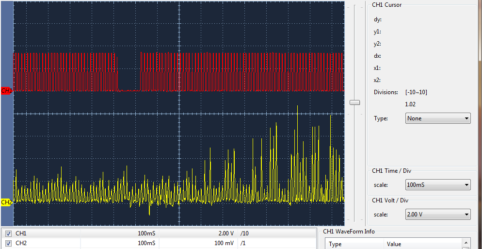
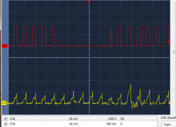
3 PWM generators (GEN_MODE_SYNC) will suddenly stop or perhaps only PWM control block outputs Null for 150-275ms (CH1). The result is all 3 phase currents CH2 randomly burst to catch up to the current lag. Have noticed this current burst LM3S8971 MCU and thought it was normal inverter noise.

Motor commutation just stops then picks back up where it left off. FOC use GPTM-0 (one shot mode) to trigger PWM control block pin state changes from ADC samples of BEMF motor phases crossing zero to commutate 3 phases. Nulls occur on all 6 PWM control block outputs in some order that does not stall a running motor yet disrupts current in a bad way. The more time spent to examine older motorware the more things discover that were not so obvious at first.

What could be causing 150ms nulls on the PWM output control block configured local updates? Note ADC sequencer (BEMF sample) holds highest priority over all sequencers, same is true for GPTM-0?

A few microseconds is acceptable Null time; 150ms = 1875 PWM pulses at 12.5Khz are randomly missing.   

Note scope rolling 500ms 100ms/cm and 20 seconds of PWM pulses (CH1) occurs prior to Null and phase burst current follows (CH2 trigger source).

2.15.2017: PWM void was caused by a bad MCU where VDD measured 240 ohms to ground and 0.2v drop on diode check.

https://e2e.ti.com/support/microcontrollers/tiva_arm/f/908/p/580563/2133645#2133645

  • Hello BP101

    Is FAULT signal being used to control the PWM signals?
  • That PWM signal is heavily aliased. The measurement of any gap is meaningless.

    Robert
  • Hi Amit,

    Wish it was simple but disabled (NO_MINPER) in the extended fault handling configured (FAULT_LATCHED). Thought is might be some kind of program branching such as fan speed GPTM-0 PWM duty interrupts. That only makes a very slight difference in the PWM0 null width. The fan speed edge counter interrupts at 960 EPS and fires GPTM-3 one shot in 1 second reload intervals inside that tick handler, has very little overhead.

    Hard to imagine the application is somehow stealing 150ms from the commutation timer. The nulls gets wider if the minimum pulse width is increased by 300ns only on pwmB. That widens null to 275ms when phase pulses are only 1us wide in each 80us period. Other wise a 700ns wide pulse the null reduces to 150ms.

    The PWM module seems to be timing out the control block MUC pin updates at the end of an non existing SW cycle, is that possible?

  • Robert:
    "The measurement of any gap is meaningless."

    Disagree, as you will notice CH2 has no Null gap and to blame the scope ADC sampling seems wrong. Scope sample window (not shown) is 500ms and CH1 only 1000 samples deep this capture.
  • BTW Robert how do you explain the phase current spikes after the PWM null void. Theory explains phase current spike would occur if suddenly PWM stops commutating the inverter.
  • Irrelevant. Take a look at the observable PWM frequency, the aliasing is painfully obvious. You cannot make any valid measurements of gap or current pulse. And there is absolutely no reason the two channels should show the same gap behavior under aliasing.

    The oscilloscope capture is meaningless, there is no useful information in it, you cannot say there is a PWM gap, you cannot say there is a pulse. If anything the current waveform argues against a PWM gap, but I'd not want assert that was the case.
  • Absurd speculation once again!  Perhaps you didn't read the Null void widens with forced changes in pulse width.

    Robert:

    >you cannot say there is a pulse. If anything the current waveform argues against a PWM gap, but I'd not want assert that was the case.

    BP101:

    There are missing pulses in the void and the phase trapezoidal wave form falls apart for 150ms when shortly after monitors indicate a current burst. BTW the average current CH2 100mv = 9-10 amps and the pulse peaks near 50 amps or 10mv/Amp. That ain't normal but only during acceleration or extremely heavy loads neither of which are occurring. All excellent indications that PWM just stops!

  • BP101 said:
    Absurd speculation once again!

    What is the sampling frequency of the oscilloscope?

  • Never should be any gap at all and that is the point 500ms/1Ksps, 1000 deep or 10k deep. Yet it don't matter the current is spiking when it should be relatively steady.
  • Robert:
    >If anything the current waveform argues against a PWM gap,
    BO101:
    That CH2 is an analog signal input near 1-5us transient response, CH2  CH1 is an digital output subject to a PWM clock and interrupts.

    Now help me figure what is stopping PWM and often driving PWM Mn0Faults at the same time.

    Has the fault Minper timer gone rouge under a latched generator fault configuration and if so why?

  • BP101 said:
    Absurd speculation once again!  Perhaps you didn't read the Null void widens with forced changes in pulse width.

    Nope, scope shows a ~6 pulses per 100mS division, that's a frequency of ~60Hz or ~ two orders of magnitude less that your 12.5kHz switching frequency. That is evidence of heavy aliasing.

    BP101 said:
    There are missing pulses in the void and the phase trapezoidal wave form falls apart for 150ms when shortly

    There is no evidence of that. If you have an oscilloscope capable of triggering on pulse width then it would be easy to actually find such a region, but not all 'scopes have that capability even if it's fairly common.

    I don't doubt you may have a current pulse but

    • You don't have any evidence of a current pulse in this capture
    • You don't have evidence that you are missing any PWM pulses

    Until you can show such missing pulses and associate them with a current pulse you are making random associations with non-demonstrated phenomenon.

    Robert

  • BP101 said:
    Robert:
    >If anything the current waveform argues against a PWM gap,
    BO101:
    That CH2 is an analog signal input near 1-5us transient response, CH2 is an digital output subject to a PWM clock and interrupts.

    Umm, what?


    Then what is CH2, you earlier said it was current. If it is digital what is it?

    BTW if it is a digital output that's further evidence of aliasing.

    BP101 said:

    Now help me figure what is stopping PWM

    As soon as you can show that it is you will be a lot closer to understanding the circumstances involved.

    Robert

  • Was typo CH1 is digital as inferred PWM and CH2 is analog. Forget about the aliasing it is what it is and also irrelevant and off topic!
  • BP101 said:
    Was typo CH1 is digital as inferred PWM and CH2 is analog

    No problem with typos, we all make them.  What is the PWM inferred from?

    BP101 said:
    Forget about the aliasing it is what it is and also irrelevant and off topic!

    Neither irrelevant nor off-topic. It renders your capture meaningless, it doesn't show what you are claiming it shows.

    Robert

  • Again current monitor sagging before peaking are direct indicators PWM stopped, phase current sags then suddenly PWM started again mid cycle and phase current jumps. How much more simple does capture need to be to indicate PWM stops for some time in CH1 null void.

    CH1 is an 80us period and scope LCD retrace so fast the human eye would miss the real time Null event and not show CH2 peaks in the same capture. That is sort of the point to show them together in the same capture.
  • BP101 said:
    Never should be any gap at all and that is the point 500ms/1Ksps, 1000 deep or 10k deep.

    Do you mean the oscilloscope has been set to collect at a rate of 1000 samples per second?

    If so, sampling a 12.5KHz PWM signal at 1000 samples per will WILL give you an aliasing problem, such that oscilloscope misses pulses.

  • The channel scan rate is 525-1000 SPS and 1k or 10k samples deep storage acquisition, independent from 500ms horizontal roll. The pulses are squashed together and runs for 10-20 seconds with average current CH2 then CH1 PWM voids and CH2 current spikes result. Explains random occurring faults being tripped from missing PWM pulses not the scope is missing pulses for 150-275ms. That would be like the grand canyon of scope error even at 1k storage acquisition.
  • BP101 said:
    That would be like the grand canyon of scope error even

    Not an oscilloscope error, aliasing. That is exactly what you sometimes see with aliasing, particularly of square waveforms such as PWM.

    Robert

    The oscilloscope is working just fine.

  • BP101 said:
    CH1 is an 80us period and scope LCD retrace so fast the human eye would miss the real time

    That's rather why you use an oscilloscope with proper triggering, it shows you events that are much faster than you could otherwise see. But if you don't use the instrument properly....

    Robert

  • Robert with all due respect you are missing the forensics in this analysis and has nothing to do with proper operation. Again you have not explained why CH2 current pulses only peak near 100mv for 10-20 seconds then suddenly and with direct injury spike to near 50 amps right after the PWM null event. That is not a result of aliasing rather a drop off in commutation periods, motor current will rise under the load of the rotor.

    That is a repeating event, so you are saying the scope acquisition memory is running out and a grand canyon gap is resulting from otherwise a normal trace roll at 500ms 100ms CH1 but only after 10-20 seconds of rolling. That just is not happening nor is CH1 aliasing so bad to even cause such an repeating event of 150ms null period in PWM pulses.

  • BP101 said:
    right after the PWM null event

    There is no evidence of a PWM null event.

    BP101 said:
    That is not a result of aliasing

    You have very strong aliasing, your conclusions are based on garbage data.

    BP101 said:
    That just is not happening nor is CH1 aliasing so bad to even cause such an repeating event of 150ms null period in PWM pulses.

    That is an assertion in contradiction to the available evidence.

    Robert

  • Might I log, "Vote # 3" for your investigation into "Aliasing?"

    If 3 (now) here - 2 of reasonably sound mind - all agree - might that cause you (some) pause?
  • Robert: That is an assertion in contradiction to the available evidence.

    BP101:

    Something is definitely making the scope void CH1 and current peak 45 amps CH2 in nearly 20 second intervals, low speed commutation 250 RPM. That same void much wider shows up 20ms/cm, 2.5ksps, 1K samples deep. Setting 20-50us/cm 25ksps 10k sampling depth seems to cover up a hiccup of PWM output control block noticed as rapid frequency over drive event in that same area.

    Saying that 500sps,100ms/cm is to slow sample rate 80us period in 30mHz band width and missing 1875 PWM pulses, is suggesting something is wrong not with the scope aliasing but with the PWM peripheral behavior. Not disagreeing there is aliasing CH1 but should never be a void unless something is seriously going wrong in the PWM output stream. That might not be detectable at 20-50us/cm if the trigger hold off is compensating or scope sampling rate/depth simply ignores the higher frequency shift of PWM control block.

    Otherwise the evidence of a distinct and repeating void points to a serious issue!   

  • Seeing a repeating void has seriously made me pause enough to pull out the Tektronix and compare findings. Aliasing is an expected result but not a repeating and wide void or when 1875 PWM pulses go missing even at 20ms/cm. If we can't trust the test instrument from China it should not have an ECE listing if it is bugged in this way but I highly doubt it is.
  • Tektronix 2436 storage scope had even larger void near 500ms CH1. Course everything looks ok with 80us PWM pulses when zoomed in accept the current peaks CH2 are mostly very high. That TEK storage scope made 1987 and channel samples at 1MSPS.

    Seems to me the NVIC is giving something else higher priority than PWM which is for the most part interrupt and priority controlled.

    Perhaps this PWM void is programmatic branching, one gut feeling. In defense of captures how could any company produce a scope with such poor sampling ability at the low end without making that clear it has limitations and will skip 1000's of samples at some frequency. Nearly 1875 samples skipped even at 2.5KSPS, 1K deep, 20ms seems to indicate the PWM output control block is not 100% occupied by the One shot BEMF trigger timer. Data sheet makes it clear BLDC can behave that way.

    Output Control Block:

    The output control block takes care of the final conditioning of the pwmA' and pwmB' signals before they go to the pins as the MnPWMn signals. Via a single register, the PWM Output Enable (PWNENABLE) register, the set of PWM signals that are actually enabled to the pins can be modified. This function can be used, for example, to perform commutation of a brushless DC motor with a single register write (and without modifying the individual PWM generators, which are modified by the feedback control loop). In addition, the updating of the bits in the PWMENABLE register can be configured to be immediate or locally or globally synchronized to the next synchronous update using the PWM Enable Update (PWMENUPD) register.

    What if the application takes priority away from PWMENABLE register control loop or even before the synchronous update occurs. Might that create a void in time of the PWM control block closed loop. Yes CH1 it is heavily aliased we all agree on that and below capture 20ms, 2.5ksps, 1K samples deep.

    Rhetorical: How could CH1 possibly miss 100ms of sampling window. The One shot commutation timer triggers modulation of the PWMENABLE register from ADC samples of BEMF crossings of code steps 1&6. The idea is to have little to no lost time in the closed loop which seems to roll voids every 20 seconds or less. Delfino dual core rings a huge bell similar issues may have occurred Piccolo embedded FOC when IOT application was running background. IOT connection is not enabled my captures but the application is printing local IOT status via USB. Yet 320kbps is the average USB transfer to bulk virtual client port on Windows desktop. Have noticed the void reduces near 25ms upon disabling USB, perhaps an indication it might be outer application loop branching or interrupts creating the condition to form a Void what ever that may be.


  • BP101 said:
    How could CH1 possibly miss 100ms of sampling window.

    Probably the same way it misses almost every other PWM transition, Even in the area where it shows transistions it's only showing 1% of them, missing the additional 1% hardly seems worth noting.

    It's called aliasing.

    BP101 said:
    In defense of captures how could any company produce a scope with such poor sampling ability

    The 'scope is working fine (Tek produces high quality instrumentation). I'm fairly confident the 'scope manual warns about aliasing, all of Tek's documentation on their DSOs that I've seen makes explicit mention and caution of this (Also all other quality manufacturers documentation that I've seen). This is a well known, well documented limitation that skilled users are expected to be able to recognize and account for.

    Robert

    Bah! Awitching should be Switching! Not going to change it now.

  • >well documented limitation that skilled users are expected to be able to recognize and account for.

    Not so fast Robert "very likely an artifact" not discussed in any manual or technical brief is highly suspicious. I don't care about the aliasing part yet the void missing data indicates something occurred out side the alias sample time frame of all other pulses and that repeats every 15-20 seconds on both scopes. 

    That capture is not from Tektronix storage but from a newer 21st century Tenma storage with 8" LCD. Both manuals don't say a word about aliasing or voids, must be something with these storage scopes. In past 1985 had a TEK 4410, 4 channel 150Mhz and never saw missing data voids like this, squashed pulse streams perhaps but never voids.

    The Tenma manual never said that it might drop entire sections of sampling in the data stream may produce reoccurring Voids every 20 seconds. Oddly the Tektronix 2436 storage does the very same thing but even longer voids.

  • BP101 said:

    >well documented limitation that skilled users are expected to be able to recognize and account for.

    Not so fast Robert "very likely an artifact" not discussed in any manual or technical brief is highly suspicious.

    Any particular reason you would expect them to discuss every possible sampling distortion caused by aliasing? Or do you just want the answer to be it's a hardware fault?

    BP101 said:
    I don't care about the aliasing part yet the void missing data indicates something occurred out side the alias sample time frame

    Balderdash. Stuff and nonsense. Utterly and completely ridiculous. The fact that aliasing is occurring means you cannot depend on the sample to accurately represent the shape or magnitude of the waveform.

    BP101 said:
    repeats every 15-20 seconds on both scopes.

    Are you under the misapprehension that aliasing does not produce repeatable waveforms? It certainly can.

    BP101 said:
    That capture is not from Tektronix storage but from a newer 21st century Tenma storage with 8" LCD.

    OK. So? If it were an analog scope you'd have something to talk about. A DSO will alias. It's part of they way they work, a fundamental limitation.

    BP101 said:
    Both manuals don't say a word about aliasing or voids, must be something with these storage scopes.

    Apparently they have become less tutorial. Certainly manuals have become less comprehensive, no longer including circuit diagrams and theory of operation sections for the internal circuitry.

    BP101 said:
    In past 1985 had a TEK 4410, 4 channel 150Mhz and never saw missing data voids like this, squashed pulse streams perhaps but never voids.

    Your limited experience is no reason to reject common knowledge nor to reject what the display itself shows for that matter.

    BP101 said:
    The Tenma manual never said that it might drop entire sections of sampling in the data stream may produce reoccurring Voids every 20 seconds

    Why on earth would it say something that odd?

    BP101 said:
    Oddly the Tektronix 2436 storage does the very same thing but even longer voids.

    Not in the least odd, considering how heavily aliased your sampling is.

    To review the evidence in the capture you presented

    • Switching Frequency 12.5kHz
    • Displayed frequency ~50 to 60Hz
      • Conclusion: very heavy aliasing, signal shape and magnitude presented are likely not to represent the actual signal. If it were not aliased you would see a solid band on the display rather than the squared waveform you presented.
    • Gap in the voltage waveform
    • No corresponding gap in the current waveform
      • Conclusion: no gap exists, the voltage waveform gap is confirmed to be an aliasing artifact.

    If you want to eliminate aliasing, then put a low pass filter on your probe. A little RC filter with a bandwidth of 1kHz would do wonders. If there is a gap it would still be obvious but the 12.5 kHz components would be considerably reduced.

    Robert

    From Rutgers

    www.google.ca/url

    Agilent Manual at Brown Univ. Pg 143

    www.brown.edu/.../2000_series_users_guide.pdf

  • >Balderdash. Stuff and nonsense. Utterly and completely ridiculous. The fact that aliasing is occurring means you cannot depend on the sample to accurately represent the shape or magnitude of the waveform.

    If that void amidst aliasing is an artifact ADC sampling all scope engineers need to post markers on CRT sample dead time start/end periods.

    Can't imagine engineer would leave out such vital information from LCD signal being sampled. So It AIN'T about the operator rather more about  engineers ignoring design limitations of their product in public disclosure according to your reasoning. Especially Tektronix 2436 storage scope 1987 cost thousands of $$ leader in the scope industry. The 2436 has every imaginable CRT readout/diagnostic testing by your reasoning it's ok to create huge voids in the sample window time for no good reason, don't think so! Small voids between compacted data are expected behavior but not grand canyon void events. 

    Therefore with all due respect your assertion such void is an artifact of aliasing should always be disclosed but has not been. I will be calling Tenma and Tektronix today and get their reason as to why never disclosed such an anomaly would occur. Likely will be told valid sample time (void) area but the average period frequency shifted above the ADC (sample hold) threshold, AKA void in channel CRT signal.

    M opinion after reviewing CH1 at high horizontal scan rates, some kind of odd (phasing) event is occurring in the PWM generators.

  • BTW:
    Amit some time ago told both CB1 and myself the ADC is not in the same clock domain as PWM peripheral. Have you ever heard of a BFO creating an IF and it seems that might be the case in void area. The void seems to be phasing pulses are 2.5khz(400us) existing far above the horizontal grid time even at 20ms so both scopes blank that area for 150ms or more.

    Commutation in theory occurs synchronous to both clocks being in phase. Perhaps at some point the BEMF samples that trigger 6 commutation steps get out of phase with PWM oscillator at the PWMENABLE register and briefly creates an IF of 2.5KHz in stead of the expected 12.5Khz.
  • BP101 said:

    >Balderdash. Stuff and nonsense. Utterly and completely ridiculous. The fact that aliasing is occurring means you cannot depend on the sample to accurately represent the shape or magnitude of the waveform.

    If that void amidst aliasing is an artifact ADC sampling all scope engineers need to post markers on CRT sample dead time start/end periods.

    It's not dead time, it's aliasing. The 'scope is sampling low portions of the PWM

    It's the nature of the signal that it is not possible for the 'scope to determine that there is a gap produced by aliasing. It might be possible to detect that aliasing is occurring by comparing the frequency content of the signal to that of the sampled data but the result would be to mark the entire sampled data as invalid.

    Given that your current signal confirms there is switching occurring in the gap it seems a trifle odd that you persist in insisting that there is no switching activity.

    BP101 said:
    So It AIN'T about the operator rather more about  engineers ignoring design limitations of their product in public disclosure according to your reasoning.

    Nope. User's of instruments MUST be aware of their limitations and when/where they are appropriate to use. Full Stop. It is your responsibility to understand, it is not the manufacturers responsibility to point out every possible misuse (that is certainly impossible in any case). This is a scientific/technical instrument, the user is expected to know how it works.

    I might like the manuals to contain more theory of operation for new users but manuals are expensive to write so I can understand why that's been set aside.

    BP101 said:
    I will be calling Tenma and Tektronix today and get their reason as to why never disclosed such an anomaly would occur.

    If all you ask is if a gap can occur in the sampling you will be told no. If you describe that you are attempting to measure a 12.5kHz signal at 100ms/div and ask if the result will reflect the 12.5kHz signal you will get a quite different answer that more accurately reflects your usage.

    Robert

    If you ask the right question you will get the answer you want. The answers relationship to your situation may be non-existent.

  • Robert your trying to make analysis far to complicated and not offer any answers on what could be causing the void condition. That is the point to fix the dang issue not continuously debate alias signal being valid. The question was vague not specific and calls for speculation and think outside the box.

    Could it be the current is actually spiking repeatedly when the PWM frequency falls instantaneously below 12.5Khz. There are 3 phases so expect analog feed back CH2 even when no PWM signal is present on CH1. We use SW to select the phase sampling being valid.

    Seems there is a pitfall in all digital scopes producing aliased signals the horizontal alias rate can not shift up in frequency. That is the channel being tied directly to the horizontal time base can not capture a pulse above the set frequency of the time base. This case the 100ms/20ms horizontal rate can not capture a 400us pulse stream once it is triggering on the primary aliased and locked in frequency 100ms/20ms. A standard scope would easily capture a 2.5khz pulses inside 12.5Khz pulses at 100ms. Not sure what has gone wrong along the line to keep the basic functionality the same when storage was touted to have so much more ability!
  • BP101 said:
    not offer any answers on what could be causing the void condition.

    I've been telling you consistently (and others have suggested it as well) that what is causing the void is aliasing. There is no void, the current signal quite nicely confirms that.

    You could easily check this by putting a low pass filter (an RC with a 1kHz corner would do nicely in your setup I think). That would show the gap if it existed and a steady quasi-DC line if it did not. You might have a little ripple aliased on it but you'd have removed most of the alias-able frequency power.

    BP101 said:
    Not sure what has gone wrong along the line to keep the basic functionality the same when storage was touted to have so much more ability!

    This is a DSO limitation that's been known for 30 years (and the major reason some people kept buying analog 'scopes).

    DSOs have a lot of advantages compared to analog 'scopes. This is one of the prices you pay for those advantages.

    One of the advantages with your setup is that you already know what the PWN frequency is. If you capture is showing a different frequency then you know you are aliased, so you have a simple check.

    Robert

  • Robert:

    >I've been telling you consistently (and others have suggested it as well) that what is causing the void is aliasing. There is no void, the current signal quite nicely confirms that.

    BP101: The roll feature even with aliasing can reveal odd things easily escape the eye at higher sample rates.  This case the evidence shows said void effects +24v dc switching power supply current limiting. Same spike CH2 occurs zoomed in but can not capture IF (2.5Khz)  at higher horizontal rates. 

    CH1 PWM trigger source and CH2 +24vdc with 2v bridge ripple when the spike sources hard current.

  • BP101 said:

    Robert:

    >I've been telling you consistently (and others have suggested it as well) that what is causing the void is aliasing. There is no void, the current signal quite nicely confirms that.

    BP101: The roll feature even with aliasing can reveal odd things easily escape the eye at higher sample rates.  

    Introducing roll doesn't suddenly make the signal valid.

    BP101 said:

    This case the evidence shows said void effects +24v dc switching power supply current limiting. Same spike CH2 occurs zoomed in but can not capture IF (2.5Khz)  at higher horizontal rates. 

    CH1 PWM trigger source and CH2 +24vdc with 2v bridge ripple when the spike sources hard current.

    Well, this is just wrong.

    Robert

  • I really find it complete wrong that you would disregard all indications of some kind of undesired PWM disturbance. That phantom disturbance even effects the power supply steady ripple every 12 seconds.

    Why on earth would anyone in this forum believe that is proper electronic behavior. Higher sweeps indicates the same disturbance has taken place at 80us, some kind of flashing PWM crash occurs spewing 80us pulses upon DC supply rail. The odd part is 12 seconds with all non-essential interrupts disabled. The only interrupts left enabled during PWMENABE register output are PWM zero count and commutation one shot timer.

    The idea is to have clean PWM and not spewing a phantom disturbance on the DC supply rail in 12 second intervals or more. 

  • BP101 said:
    I really find it complete wrong that you would disregard all indications of some kind of undesired PWM disturbance.

    There are no indications of undesired PWM influence. Again aliasing.

    BP101 said:
    That phantom disturbance even effects the power supply steady ripple every 12 seconds.

    Nope. Again aliasing.

    BP101 said:
    Higher sweeps indicates the same disturbance has taken place at 80us

    So show us some properly triggered scans at 20uS/Div. Now 80uS is about the PWM frequency so you would expect signal at that timescale.

    Using a DC supply to run a motor is fraught with problems to begin with. But that's a separate post.

    Robert

  • Seem you are trying to relate alias results from scope ADC slower sample of a faster time slice (80us pulses) being squashed compressed in a 20ms sample window produces useless information. So the current peaks CH2 were actually only a compressed sample of a much wider signal profile. The bad part is the trigger level set near or just above 100mv CH2 @20us-200ns sweep will not hold off rolling but only at 500mv peaks or above. That makes CH2 +500mv peaks appear in my mind as some king of current surging and does not represent the average current profile. Agree +24 DC off line supply complicates and the 2KW linear (22,000uf caps) 470uf near inverter B+, produces three dv/dt rings/pulse @130 VDC 9 amp load. Sadly 150 volt batteries were not included by Santa's helpers, future lists asked 300 volt batteries but even spending millions $$ R&D he must need more time. Though Toyota Incite runs 600 volts, data sheet omits how produced but suspect AC generator hybrid or yet another battery monopoly.

    What was causing CH1 void:  The watchdog timer being punched several times every 80us in the closed loop PWMENABLE register. Same watchdog timer was again punched every 40us in another GPTM producing 25Khz PWM cooling fan speed control. Even with dogs priority set below GPTM one shot commutation timer (closed loop) the application was repeatedly branching into dog timer peripheral leaving numerous voids in PWM. Single stepping (F5) with several break points through out closed loop did not reveal SW branching dog timer, CCS debug interrupts enabled. Had to put extra dog punches in SW when GPTM edge count was past configured to interrupt every 2 edges of fans tachometer signal. GPTM edge count for taco signal now does match interrupt every 50 - 940 edges per second. All but 1 dog punch (timeout 333ms) could be removed in the closed loop.   

    Things are much better but seems Santa has been naughty.

  • >This is a DSO limitation that's been known for 30 years (and the major reason some people kept buying analog 'scopes).

    DSOs have a lot of advantages compared to analog 'scopes. This is one of the prices you pay for those advantages.

    I totally disagree it is not the scope user who should know the limitation of an instrument when it has not been disclosed such functional limitation may occur anywhere in user text. By that excuse my electric car might accelerate out of control and catch on fire but I should know that can occur.

    Perhaps scope vendors should implement some kind of sample hold compression for low speed signals by extrapolating data in null areas. Always to blame aliasing not inform user the scopes ADC may have failed to compress an entire sample time 150ms seems not the case here

    One idea might be to display Frequency out of range (FOR) in void area. There was some kind of frequency mayhem occurring 150ms void now corrected. The application branching away from PWMENABLE register to punch watchdog timer was messing with PWM output control block in an unusual way that could not be detected by the human eye at 20us-200ns horizontal sweep.
  • BP101 said:
    Seem you are trying to relate alias results from scope ADC slower sample of a faster time slice (80us pulses) being squashed compressed in a 20ms sample window produces useless information

    Not compressed, aliased. A very different thing. And yes, you are catching on, the result is meaningless. I really thought I was being explicit about that, there wasn't any need to search for subtle implications.

    BP101 said:
    What was causing CH1 void:  The watchdog timer being punched several times every 80us in the closed loop

    CH2 contradicts this.

    Also if the watchdog is causing this kind of problem you have far bigger problems than a loss of PWM.

    Robert

  • BP101 said:
    >This is a DSO limitation that's been known for 30 years (and the major reason some people kept buying analog 'scopes).

    DSOs have a lot of advantages compared to analog 'scopes. This is one of the prices you pay for those advantages.

    I totally disagree it is not the scope user who should know the limitation of an instrument when it has not been disclosed such functional limitation

    Your lack of knowledge is not the toolmaker's fault. It's not as if the information wasn't available and even presented to you by multiple people within this thread and IIRC other threads.

    BP101 said:
    By that excuse my electric car might accelerate out of control and catch on fire but I should know that can occur.

    A better analogy would be you not knowing you had to manually change gears in an vehicle with a manual transmission.

    BP101 said:
    Perhaps scope vendors should implement some kind of sample hold compression for low speed signals by extrapolating data in null areas.

    It's called a low pass filter and whether you use an analog or digital 'scope that is something you are expected to provide.

    BP101 said:
    One idea might be to display Frequency out of range (FOR) in void area.

    They'd have to be able to detect that, which would mean sampling at a far higher rate. If they can do that then they can display the result and they do not need the warning. Basically if you can produce a warning, you probably don't need one.

    BP101 said:
    The application branching away from PWMENABLE register to punch watchdog timer was messing with PWM output control block in an unusual way

    This part isn't believable. Branches in the application will not affect the PWM hardware.

    BP101 said:
    that could not be detected by the human eye at 20us-200ns horizontal sweep.

    And this part is just silly.

    Robert

  • A graphics term (aliased) is being used incorrectly to characterize ADC samples of (compressed signal data) captured directly inside the horizontal sweep time of each sample. Vector graphics dot dithering of 3D images are often (aliased), extrapolating data algorithms improve image quality by smooth any apparent stepping of dots in graphics images comprised of diagonal lines. Dot dithering or aliasing is not occurring in these scope captures and the graphics controller video quality term (aliased) does not seem to apply or should not. The scope channel output to LCD is a result of ADC sample data (compression) captured in the horizontal sweeping of the originating signal, not that the dots were made to appear smoother via an LCD dithering algorithm because of poor video quality.

    Again constant setting of watch dog timer was interrupting PWMENABLE synchronization and breaking the closed loop interrupt cycles of the PWM generators zero flag. PWMENABLE cycles are not directly controlled by PWM generators, rather a separate GPTM triggers ADC samples used to commute the PWMENABLE register.  That closed loop cycle should remain synchronous but was at times asynchronous producing large (voids) in sample data. Best guess is the 4:4 interrupt priority split requires NVIC to give processor time to any other peripherals INTPEND that have the same priority but a lower interrupt number event of a tie. What ever it is fixed no more large voids are occurring.  

  • BP101 said:
    A graphics term (aliased)

    Nope, not referring to a graphics term at all. Although some of the underlying principles are the same. In both cases the solution is, in effect, to apply a low pass filter to remove high frequency content before sampling.

    Here's another reference, this time from NI with some notes on filtering to reduce aliasing

    zone.ni.com/.../

    BP101 said:
    Again constant setting of watch dog timer

    You should not be modifying the timer constantly. The period should be set once and then left.

    BP101 said:
    Again constant setting of watch dog timer was interrupting PWMENABLE synchronization and breaking the closed loop interrupt cycles of the PWM generators zero flag.

    Still not believable. You are saying that writing a value to the watchdog registers affects the PWM peripheral at a different address. A silicon error this significant should have been seen by others and would probably have other effects, You will need to generate a test case to demonstrate this.

    BP101 said:
    Best guess is the 4:4 interrupt priority split requires NVIC to give processor time to any other peripherals INTPEND that have the same priority but a lower interrupt number event of a tie.

    That makes no sense, the NVIC does not give processor time to the peripherals. One of the advantages of HW peripherals is that they run without processor intervention. All the NVIC does is interrupt the processor for an interrupt routine written by you. It will give execution to the highest currently enabled interrupt subject to the priority scheme. It does no form of round robin switching, it does not give HW processor time to a peripheral.

    BP101 said:
    What ever it is fixed no more large voids are occurring.  

    One of the side effects of aliasing is that small, even insignificant changes in the input signal can produce apparently large changes in the sampled signal. Your signal very likely has not changed at all.

    Robert

  • >Nope, not referring to a graphics term at all.

    Scope guys copped a video term and change the meaning to fit something with entirely different behavior. That scope behavior is compression or skewing time in the sample period since the original signal is more often steady state unless it is video with back porch and all. Even at 500SPS 100ms sweep that is extremely fast sampling and the ADC sample hold skips over peaks in the faster frequency time or skews over sample time slices in the slower horizontal sweep. The term aliasing infers a video term and not what is occurring at 500SPS to the LCD screen. That is more like time skewing of the ADC sample window that fails to lock onto the faster frequency and lags behind skipping peaks in the signal due to sample hold and acquisition recovery times. But not to beat a dead horse Alias it remains. The scope channel amplifier should already have a low pass filter or modifies the sample hold times for acquisition of slower frequency signals.

    >You should not be modifying the timer constantly. The period should be set once and then left

    It was even more necessary when the fan taco edge counter was interrupting every 2 edge counts. The watchdog was set to expire every 150ms and unless the (application) cycle punches dog it expires. Even during idle the watchdog is constantly being updated and takes a lot of clock time from other parts of the application. That is so the application punches the dog to keep it quiet and it expires if the application loop runs to slow, stops or hangs up.

    >That makes no sense, the NVIC does not give processor time to the peripherals.

    Agree in part yet the application uses MCU instruction time to punch the dog and peripherals are priority governed by NVIC in a closed loop reload of the PWM counters. So the application can hog clock cycles and not service PWM peripheral. Again PWMENABLE register is not gated by the PWM peripheral rather GPTM one shot triggers application to commutate PWMENABLE around other
    interrupt priority levels where the watch dog is imbedded in the closed loop. Don't forget after the interrupt is cleared another priority interrupt can push a return address on the stack and PC can jump to the next task in the prefetch instruction buffer. That can yank the application all over the playing field if certain tasks are not well meshed by NVIC priory grouping logic. NVIC holds the highest priority along with the SYSTICK timer who has no lower priority than NVIC.
  • BP101 said:
    But not to beat a dead horse

    Yet - right after your promise - both the (dead) horse and scope maker are "scolded" for not designing to, "BP specification!"   (surely you've alerted them to such need...)

    If - as you claim - a, "Low Pass Filter" should be permanently emplaced - how then would frequencies "above" F0 be displayed?

    Perhaps that (dead) horse became first injured when, "Racing thru the VOID" - when the concept of Aliasing was under (your) challenge...

  • BP101 said:
    >Nope, not referring to a graphics term at all.

    Scope guys copped a video term and change the meaning to fit something with entirely different behavior.

    Nonsense you are wrong on both parts of this claim, the theory and usage predates both image processing and DSOs as near as I can tell. The two are also based on fundamentally the same principles, and both involve low pass filtering.

    The fundamental theoretical background was laid before WW II

    en.wikipedia.org/.../Nyquist–Shannon_sampling_theorem

    And the term was used for the same effect in Radio Frequency receivers

    en.wikipedia.org/.../Aliasing

    And there are other usages of alias and aliasing that are quite different.

    BP101 said:
    That scope behavior is compression or skewing time in the sample period since the original signal is more often steady state unless it is video with back porch and all. Even at 500SPS 100ms sweep that is extremely fast sampling and the ADC sample hold skips over peaks in the faster frequency time or skews over sample time slices in the slower horizontal sweep.

    No, just no.

    BP101 said:
    The term aliasing infers a video term

    No, and it doesn't suggest it either.

    BP101 said:
    The scope channel amplifier should already have a low pass filter or modifies the sample hold times for acquisition of slower frequency signals.

    Are you suggesting the 'scope manufacturers provide dozens of switchable low pass filters. Tell me what should their bandpasses be? How should the phase delay behave? Maybe they should be minimal ripple filters instead?  One size does not fit all.

    BP101 said:
    >You should not be modifying the timer constantly. The period should be set once and then left

    It was even more necessary when the fan taco edge counter was interrupting every 2 edge counts.

    If it's necessary to modify the watchdog time you are doing it wrong.

    BP101 said:
    That is so the application punches the dog to keep it quiet and it expires if the application loop runs to slow, stops or hangs up.

    Yes, that's how a watchdog works but it is not necessary to continually change its time. Feeding the dog is a matter of a few instructions. A few more if you implement a layered watchdog. You should never have an interrupt handler for the watchdog.

    BP101 said:
    >That makes no sense, the NVIC does not give processor time to the peripherals.

    Agree in part yet the application uses MCU instruction time to punch the dog

    Which has nothing to do with the NVIC

    BP101 said:
    peripherals are priority governed by NVIC in a closed loop reload of the PWM counters.

    No, the NVIC plays no role in how the PWM counters reload.

    BP101 said:
    So the application can hog clock cycles and not service PWM peripheral.

    The PWM peripheral runs independently of the CPU and NVIC.

    BP101 said:
    Again PWMENABLE register is not gated by the PWM peripheral rather GPTM one shot triggers application to commutate PWMENABLE around other
    interrupt priority levels where the watch dog is imbedded in the closed loop. Don't forget after the interrupt is cleared another priority interrupt can push a return address on the stack and PC can jump to the next task in the prefetch instruction buffer. That can yank the application all over the playing field if certain tasks are not well meshed by NVIC priory grouping logic.

    It sounds like you don't know how to set up your priorities.

    BP101 said:
    NVIC holds the highest priority along with the SYSTICK timer who has no lower priority than NVIC.

    NVIC does not have a priority. It makes no sense for it to have one. SYSTICK priority is not set in stone either. Depending on how you are using it there is a very good argument for making it one of the lowest priorities in the system, certainly it should be lower priority than those interrupts that occur more frequently.

    Robert

  • Robert Adsett72 said:
    BP101
    Again PWMENABLE register is not gated by the PWM peripheral rather GPTM one shot triggers application to commutate PWMENABLE around other
    interrupt priority levels where the watch dog is imbedded in the closed loop. Don't forget after the interrupt is cleared another priority interrupt can push a return address on the stack and PC can jump to the next task in the prefetch instruction buffer. That can yank the application all over the playing field if certain tasks are not well meshed by NVIC priory grouping logic.

    It sounds like you don't know how to set up your priorities.

    BTW, for this, look up Rate Monotonic Analysis.

    Robert

  • Your several claims of required low pass filtering being external to scope in my view article infers to be required and present in the ADC circuit of your link aliasing definition. DSO better have such low pass filtering built part of horizontal sweeps lower frequency to account of slower ADC sample acquisition hold times. Hard to believe any argument (term aliasing) pre existing WW2, might expect such in the vacuum tube era.

    NVIC most definitely has control over PWM zero flag interrupt priority queuing and another interrupt even lower rank can take focus away from the PWM peripheral. That is especially true in any interrupt driven application where SW is only the throttle to the HW ability and speed to process said interrupts. NVIC priority queuing can only do so much if the application execution cycles repeatedly take focus away from a peripherals pended flags in any closed loop. 

    Your aliasing PWM void not valid argument is only half founded but does bring some interesting food for thought that scopes and mankind have a lot of growth potential in the next 100 years.

  • >If - as you claim - a, "Low Pass Filter" should be permanently emplaced - how then would frequencies "above" F0 be displayed?

    I hear digital controlled filters were the talk of the day a decade ago.
  • >NVIC does not have a priority. It makes no sense for it to have one. SYSTICK priority is not set in stone either. Depending on how you are using it there is a very good argument for making it one of the lowest priorities in the system, certainly it should be lower priority than those interrupts that occur more frequently.

    Disagree - NVIC has local bus priority over (any peripheral) on the MCU local bus and SYSTICK timer holds highest of priorities in that it has no priority assignment other than fault handler being SYSTICK exists at the NVIC level! Reason why you don't have to clear a SYSTIC interrupt is that NVIC unpends the handler internally.