This thread has been locked.

If you have a related question, please click the "Ask a related question" button in the top right corner. The newly created question will be automatically linked to this question.

TM4C1294NCPDT: TM4C I2C high speed mode setting problem.

Part Number: TM4C1294NCPDT
Other Parts Discussed in Thread: TMP102

Hi

I tested ektm4c129 and tmp102evm.

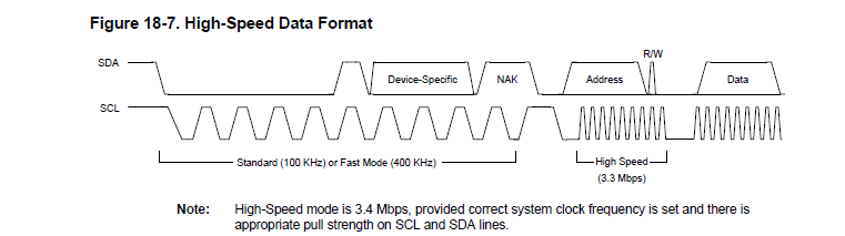
I am setting ektm4c129 with I2C High speed mode.

I can't set  TM4C I2C   any value except  any value except table 18-3 value.

TM4C's I2C occured error.

I want  2Mhz of I2C transmissim value .

How can I setting value???

Tm4c High-speed mode can support 2.7Mhz (1285page)

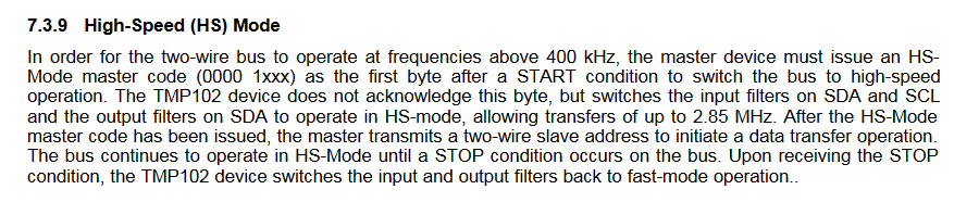
TMP102's highspeed mode can support 2.85Mhz

I am setting TM4C's 2.77Mhz trasmission

but I read 0x00 tmp102's value with setting 2.77Mhz trasmission.

I think It meets tmp102's transmission specification.

what's problem??.

I attached my code.

tmp102_hs_v2.zip

 Br

Yj.kim

  • Have you zoomed in and looked at the I2C signals with a scope? Is SCL at 2.77MHz when in HS mode? Is the issue with the timing of the SDA signal from the TMP102, or is the TMP102 not responding at all? Have you tried interfacing with the TMP102 at 400KHz first, just to make sure your software is correct?
  • My  tested  code is  "ektm4c129_i2c_master_hs.c "  at previous post.

    It set below prameter.

    system clock:50Mhz, timer Period:0x02 , Transmisson: 2.77Mhz

    when I test I2C stand mode, It has no problem. 

    I tested new code and  parameter below link.

    system clock:120Mhz, timer Period:0x07 , Transmisson: 2.5Mhz.

    It has also problem.

    I read value from tmp102 and Only I recive 1 byte.

    If it read 2byte. from tmp102 in Nomal state. 

    It reiceve I2C_MASTER_INT_NACK massage and then stop. so don't receve message.

    ektm4c129_i2c_master_hs.c
    //*****************************************************************************
    //
    // ektm4c129_i2c_master_hs.c - I2C Master with High Speed Data Transfer
    //
    // Copyright (c) 2013-2015 Texas Instruments Incorporated.  All rights reserved.
    // Software License Agreement
    // 
    // Texas Instruments (TI) is supplying this software for use solely and
    // exclusively on TI's microcontroller products. The software is owned by
    // TI and/or its suppliers, and is protected under applicable copyright
    // laws. You may not combine this software with "viral" open-source
    // software in order to form a larger program.
    // 
    // THIS SOFTWARE IS PROVIDED "AS IS" AND WITH ALL FAULTS.
    // NO WARRANTIES, WHETHER EXPRESS, IMPLIED OR STATUTORY, INCLUDING, BUT
    // NOT LIMITED TO, IMPLIED WARRANTIES OF MERCHANTABILITY AND FITNESS FOR
    // A PARTICULAR PURPOSE APPLY TO THIS SOFTWARE. TI SHALL NOT, UNDER ANY
    // CIRCUMSTANCES, BE LIABLE FOR SPECIAL, INCIDENTAL, OR CONSEQUENTIAL
    // DAMAGES, FOR ANY REASON WHATSOEVER.
    // 
    // This is part of revision 2.1.1.71 of the EK-TM4C1294XL Firmware Package.
    //
    //*****************************************************************************
    #include <stdint.h>
    #include <stdbool.h>
    #include "inc/hw_types.h"
    #include "inc/hw_ints.h"
    #include "inc/hw_memmap.h"
    #include "driverlib/gpio.h"
    #include "driverlib/i2c.h"
    #include "driverlib/interrupt.h"
    #include "driverlib/pin_map.h"
    #include "driverlib/sysctl.h"
    #include "driverlib/uart.h"
    #include "utils/random.h"
    #include "utils/uartstdio.h"
    #include "inc/hw_i2c.h"
    //*****************************************************************************
    //
    //! \addtogroup example_list
    //! <h1>ektm4c129_i2c_master_hs (ektm4c129_i2c_master_hs)</h1>
    //!
    //! A Simple I2C Master Code for Performing Data Transfer with a high speed
    //! capable Slave using Interrupts
    //
    //*****************************************************************************
    
    //*****************************************************************************
    //
    // Define for I2C Module
    //
    //*****************************************************************************
    #define HS_PREAMBLE       0x07
    #define SLAVE_ADDRESS_EXT 0x48
    #define NUM_OF_I2CBYTES   255
    
    //*****************************************************************************
    //
    // Enumerated Data Types for Master State Machine
    //
    //*****************************************************************************
    enum I2C_MASTER_STATE
    {
    	I2C_HS_IDLE = 0,
    	I2C_HS_PREAMBLE,
    	I2C_HS_TX,
    	I2C_HS_RX,
    	I2C_HS_STOP,
    	I2C_ERR_STATE
    };
    
    //*****************************************************************************
    //
    // Global variable for Delay Count
    //
    //*****************************************************************************
    volatile uint8_t  g_ui8MasterTxData[NUM_OF_I2CBYTES];
    volatile uint8_t  g_ui8MasterRxData[NUM_OF_I2CBYTES];
    volatile uint32_t g_ui8ReadCount	= 0;
    volatile uint32_t g_ui8WriteCount	= 0;
    volatile uint8_t  g_ui8MasterCurrState;
    volatile uint8_t  g_ui8MasterPrevState;
    volatile bool     g_bI2CDirection;
    volatile uint8_t  g_ui8MasterBytes  	 = NUM_OF_I2CBYTES;
    volatile uint8_t  g_ui8MasterBytesLength = NUM_OF_I2CBYTES;
    
    //*****************************************************************************
    //
    // Interrupt Handler for I2C Master Interface
    //
    //*****************************************************************************
    void
    I2C7IntHandler(void)
    {
    	uint32_t ui32I2CMasterInterruptStatus;
    
    	//
    	// Toggle PL4 High to Indicate Entry to ISR
    	//
    	GPIOPinWrite(GPIO_PORTL_BASE, GPIO_PIN_4, GPIO_PIN_4);
    
    	//
    	// Get the masked interrupt status and clear the flags
    	//
    	ui32I2CMasterInterruptStatus = I2CMasterIntStatusEx(I2C7_BASE, true);
    	I2CMasterIntClearEx(I2C7_BASE, ui32I2CMasterInterruptStatus);
    
    	//
    	// Execute the State Machine
    	//
    	switch (g_ui8MasterCurrState) {
    	case I2C_HS_IDLE:
    		//
    		// Move from IDLE to PREAMBLE State
    		//
    		g_ui8MasterPrevState = g_ui8MasterCurrState;
    		g_ui8MasterCurrState = I2C_HS_PREAMBLE;
    
    		//
    		// Send High Speed Preamble on the Bus
    		//
    		I2CMasterSlaveAddrSet(I2C7_BASE, HS_PREAMBLE, true);
    		I2CMasterControl(I2C7_BASE, I2C_MASTER_CMD_HS_MASTER_CODE_SEND);
    		break;
    	case I2C_HS_PREAMBLE:
    
    		//
    		// If Preamble is NAK then check direction flag and
    		// move to TX or RX States
    		//
    		if(ui32I2CMasterInterruptStatus & I2C_MASTER_INT_NACK)
    		{
    			//
    			// Move the current state to the previous state
    			//
    			g_ui8MasterPrevState = g_ui8MasterCurrState;
    
    			if(!g_bI2CDirection)
    			{
    				g_ui8MasterCurrState = I2C_HS_TX;
    
    				//
    				// Send the Slave Address with RnW as Transmit
    				// and First Data Byte. Based on Number of bytes the
    				// command would be either START or FINISH
    				//
    				I2CMasterSlaveAddrSet(I2C7_BASE, SLAVE_ADDRESS_EXT, false);
    				I2CMasterDataPut(I2C7_BASE, g_ui8MasterTxData[g_ui8MasterBytes++]);
    				if(g_ui8MasterBytes == g_ui8MasterBytesLength)
    				{
    					I2CMasterControl(I2C7_BASE, I2C_MASTER_CMD_SINGLE_SEND);
    				}
    				else
    				{
    					I2CMasterControl(I2C7_BASE, I2C_MASTER_CMD_BURST_SEND_START);
    				}
    			}
    			else
    			{
    				g_ui8MasterCurrState = I2C_HS_RX;
    
    				//
    				// Send the Slave Address with RnW as Receive. If only byte is
    				// to be received then send FINISH else send START
    				//
    				I2CMasterSlaveAddrSet(I2C7_BASE, SLAVE_ADDRESS_EXT, true);
    				if(g_ui8MasterBytesLength == 1)
    				{
    					I2CMasterControl(I2C7_BASE, I2C_MASTER_CMD_SINGLE_RECEIVE);
    				}
    				else
    				{
    					I2CMasterControl(I2C7_BASE, I2C_MASTER_CMD_BURST_RECEIVE_START);
    				}
    			}
    		}
    		//
    		// if ACK then go to error state and log prev state
    		//
    		else
    		{
    			g_ui8MasterPrevState = g_ui8MasterCurrState;
    			g_ui8MasterCurrState = I2C_ERR_STATE;
    		}
    
    		break;
    	case I2C_HS_TX:
    		//
    		// Move the current state to the previous state
    		// Else continue with the transmission till last byte
    		//
    		g_ui8MasterPrevState = g_ui8MasterCurrState;
    
    		//
    		// If Address or Data has been NAK'ed then go to stop state
    		// If a Stop condition is seen due to number of bytes getting
    		// done then move to STOP state
    		//
    		if(ui32I2CMasterInterruptStatus & I2C_MASTER_INT_NACK)
    		{
    			g_ui8MasterCurrState = I2C_HS_STOP;
    		}
    		else if(ui32I2CMasterInterruptStatus & I2C_MASTER_INT_STOP)
    		{
    			g_ui8MasterCurrState = I2C_HS_STOP;
    		}
    		else
    		{
    			I2CMasterDataPut(I2C7_BASE, g_ui8MasterTxData[g_ui8MasterBytes++]);
    			if(g_ui8MasterBytes == g_ui8MasterBytesLength)
    			{
    				I2CMasterControl(I2C7_BASE, I2C_MASTER_CMD_BURST_SEND_FINISH);
    			}
    			else
    			{
    				I2CMasterControl(I2C7_BASE, I2C_MASTER_CMD_BURST_SEND_CONT);
    			}
    
    		}
    
    		break;
    	case I2C_HS_RX:
    		//
    		// Move the current state to the previous state
    		// Else continue with the transmission till last byte
    		//
    		g_ui8MasterPrevState = g_ui8MasterCurrState;
    
    		//
    		// If Address has been NAK'ed then go to stop state
    		// If a Stop condition is seen due to number of bytes getting
    		// done then move to STOP state and read the last data byte
    		//
    		if(ui32I2CMasterInterruptStatus & I2C_MASTER_INT_NACK)
    		{
    			g_ui8MasterCurrState = I2C_HS_STOP;
    		}
    		else if(ui32I2CMasterInterruptStatus & I2C_MASTER_INT_STOP)
    		{
    			g_ui8MasterCurrState = I2C_HS_STOP;
    			g_ui8MasterRxData[g_ui8MasterBytes++] = I2CMasterDataGet(I2C7_BASE);
    		}
    		else
    		{
    			//
    			// Read the byte from I2C Buffer and decrement the number
    			// of bytes counter to see if end has been reached or not
    			//
    			g_ui8MasterRxData[g_ui8MasterBytes++] = I2CMasterDataGet(I2C7_BASE);
    
    			//
    			// If end then NAK the byte and put Stop. Else continue
    			// with ACK of the current byte and receive the next byte
    			//
    			if(g_ui8MasterBytes == g_ui8MasterBytesLength)
    			{
    				//
    				// Do Nothing... The Transaction is over.
    				//
    				g_ui8MasterCurrState = I2C_HS_STOP;
    			}
    			else if(g_ui8MasterBytes == (g_ui8MasterBytesLength - 1))
    			{
    				I2CMasterControl(I2C7_BASE, I2C_MASTER_CMD_BURST_RECEIVE_FINISH);
    			}
    			else
    			{
    				I2CMasterControl(I2C7_BASE, I2C_MASTER_CMD_BURST_RECEIVE_CONT);
    			}
    		}
    
    		break;
    	case I2C_HS_STOP:
    		//
    		// Move the current state to the previous state
    		// Else continue with the transmission till last byte
    		//
    		g_ui8MasterPrevState = g_ui8MasterCurrState;
    
    		break;
    	case I2C_ERR_STATE:
    		g_ui8MasterCurrState = I2C_ERR_STATE;
    		break;
    	default:
    		g_ui8MasterCurrState = I2C_ERR_STATE;
    		break;
    	}
    
    	//
    	// Toggle PL4 Low to Indicate Exit from ISR
    	//
    	GPIOPinWrite(GPIO_PORTL_BASE, GPIO_PIN_4, 0x0);
    }
    
    //*****************************************************************************
    //
    // This function sets up UART0 to be used for a console to display information
    // as the example is running.
    //
    //*****************************************************************************
    uint16_t ReadTmpI2C(void)
    {
        uint32_t txData=0x00;
        uint16_t        temperature;
        uint32_t rxData[2]={0x00,0x00};
    
        //


        temperature = (g_ui8MasterRxData[0] << 4) | (g_ui8MasterRxData[1] >> 4);
     //   UARTprintf("Read data %x ,%x \n",rxData[0],rxData[1] );
          /*
           * If the MSB is set '1', then we have a 2's complement
           * negative value which needs to be sign extended
           */
          if (g_ui8MasterRxData[0] & 0x80) {
              temperature |= 0xF000;
          }
          UARTprintf("rx_0[%x], rx_1[%x]\n", g_ui8MasterRxData[0], g_ui8MasterRxData[1]);
         /*
          * For simplicity, divide the temperature value by 32 to get rid of
          * the decimal precision; see TI's TMP006 datasheet
          */
          temperature /= 16;
    
          return temperature;
    
    }
    
    void
    InitConsole(void)
    {
        //
        // Enable GPIO port A which is used for UART0 pins.
        // TODO: change this to whichever GPIO port you are using.
        //
        SysCtlPeripheralEnable(SYSCTL_PERIPH_GPIOA);
    
        //
        // Configure the pin muxing for UART0 functions on port A0 and A1.
        // This step is not necessary if your part does not support pin muxing.
        // TODO: change this to select the port/pin you are using.
        //
        GPIOPinConfigure(GPIO_PA0_U0RX);
        GPIOPinConfigure(GPIO_PA1_U0TX);
    
        //
        // Enable UART0 so that we can configure the clock.
        //
        SysCtlPeripheralEnable(SYSCTL_PERIPH_UART0);
    
        //
        // Use the internal 16MHz oscillator as the UART clock source.
        //
        UARTClockSourceSet(UART0_BASE, UART_CLOCK_PIOSC);
    
        //
        // Select the alternate (UART) function for these pins.
        // TODO: change this to select the port/pin you are using.
        //
        GPIOPinTypeUART(GPIO_PORTA_BASE, GPIO_PIN_0 | GPIO_PIN_1);
    
        //
        // Initialize the UART for console I/O.
        //
        UARTStdioConfig(0, 115200, 16000000);
    }
    
    //*****************************************************************************
    //
    // Main Program to Configure the I2C Master
    //
    //*****************************************************************************
    int
    main(void)
    {
    	uint32_t ui32SysClock;
    	uint8_t  ui8Count;
    	    uint32_t ui32TPR;
    	   uint32_t ui32Index;
    
        //
        // Set up the serial console to use for displaying messages.  This is
        // just for this example program and is not needed for EPI operation.
        //
        InitConsole();
    
        //
        // Display the setup on the console.
        //
        UARTprintf("\033[2J\033[H");
        UARTprintf("\r\nExample Code for I2C Master with");
        UARTprintf("\nInterrupt and HS Data Transfer\n\n");
    
    	//
    	// Enable GPIO for Configuring the I2C Interface Pins
    	//
    	SysCtlPeripheralEnable(SYSCTL_PERIPH_GPIOL);
    	SysCtlPeripheralEnable(SYSCTL_PERIPH_GPIOK);
    
    	//
    	// Wait for the Peripheral to be ready for programming
    	//
    	while(!SysCtlPeripheralReady(SYSCTL_PERIPH_GPIOL)
    			|| !SysCtlPeripheralReady(SYSCTL_PERIPH_GPIOK));
    	SysCtlPeripheralEnable(SYSCTL_PERIPH_I2C7);
        SysCtlPeripheralEnable(SYSCTL_PERIPH_GPIOD);
        while(!SysCtlPeripheralReady(SYSCTL_PERIPH_GPIOD));
    
    
        /* Configure the appropriate pins to be I2C instead of GPIO. */
    
        SysCtlPeripheralDisable(SYSCTL_PERIPH_I2C7);
        SysCtlPeripheralReset(SYSCTL_PERIPH_I2C7);
        SysCtlPeripheralEnable(SYSCTL_PERIPH_I2C7);
    
        while(!SysCtlPeripheralReady(SYSCTL_PERIPH_I2C7));
    
    	//
    	// Configure Pins for I2C7 Master Interface
    	//
        GPIOPinConfigure(GPIO_PD0_I2C7SCL);
        GPIOPinConfigure(GPIO_PD1_I2C7SDA);
        GPIOPinTypeI2CSCL(GPIO_PORTD_BASE, GPIO_PIN_0);
        GPIOPinTypeI2C(GPIO_PORTD_BASE, GPIO_PIN_1);
    
    
    	//
    	// Configure Pins for I2C3 Slave Interface
    	//
    	GPIOPinConfigure(GPIO_PK4_I2C3SCL);
    	GPIOPinConfigure(GPIO_PK5_I2C3SDA);
    	GPIOPinTypeI2C(GPIO_PORTK_BASE, GPIO_PIN_5);
    	GPIOPinTypeI2CSCL(GPIO_PORTL_BASE, GPIO_PIN_4);
    
    	//
    	// Configure GPIO Pin PL4 for Interrupt Time Processing
    	//
    	GPIOPinTypeGPIOOutput(GPIO_PORTL_BASE, GPIO_PIN_4);
    	GPIOPinWrite(GPIO_PORTL_BASE, GPIO_PIN_4, 0x0);
    
        //
        // Setup System Clock for 120MHz
        //
    	ui32SysClock = SysCtlClockFreqSet((SYSCTL_OSC_MAIN | SYSCTL_USE_PLL | SYSCTL_XTAL_25MHZ |
                            SYSCTL_CFG_VCO_480), 120000000);


    	//
    	// Stop the Clock, Reset and Enable I2C Module
    	// in Master Function
    	//
    	SysCtlPeripheralDisable(SYSCTL_PERIPH_I2C7);
    	SysCtlPeripheralReset(SYSCTL_PERIPH_I2C7);
    	SysCtlPeripheralEnable(SYSCTL_PERIPH_I2C7);
    
    	//
    	// Wait for the Peripheral to be ready for programming
    	//
    	while(!SysCtlPeripheralReady(SYSCTL_PERIPH_I2C7));
    
    	//
    	// Initialize and Configure the Master Module
    	//
    	I2CMasterInitExpClk(I2C7_BASE, ui32SysClock, false);
    
    	ui32TPR=((ui32SysClock + (2 * 3 * 2500000) - 1) /(2 * 3 * 2500000)) - 1;
    
        UARTprintf("ui32TPR :%x\n",I2C_MTPR_HS |  ui32TPR);
        HWREG(I2C7_BASE+I2C_O_MTPR) = I2C_MTPR_HS | ui32TPR;
    
    	//
    	// Enable Interrupts for Arbitration Lost, Stop, NAK, Clock Low
    	// Timeout and Data.
    	//
    	I2CMasterIntEnableEx(I2C7_BASE, (I2C_MASTER_INT_ARB_LOST |
    			I2C_MASTER_INT_STOP | I2C_MASTER_INT_NACK |
    			I2C_MASTER_INT_TIMEOUT | I2C_MASTER_INT_DATA));
    	I2CIntRegister(I2C7_BASE,I2C7IntHandler);
    
    	//
    	// Enable the Interrupt in the NVIC from I2C Master
    	//
    	IntEnable(INT_I2C7);
    
    	//
    	// Enable the Glitch Filter. Writting a value 0 will
    	// disable the glitch filter
    	// I2C_MASTER_GLITCH_FILTER_DISABLED
    	// I2C_MASTER_GLITCH_FILTER_1
    	// I2C_MASTER_GLITCH_FILTER_2 : Ideal Value when in HS Mode
    	//                              for 120MHz clock
    	// I2C_MASTER_GLITCH_FILTER_4
    	// I2C_MASTER_GLITCH_FILTER_8 : Ideal Value when in Std,
    	// 								Fast, Fast+ for 120MHz clock
    	// I2C_MASTER_GLITCH_FILTER_16
    	// I2C_MASTER_GLITCH_FILTER_32
    	//
    	I2CMasterGlitchFilterConfigSet(I2C7_BASE, I2C_MASTER_GLITCH_FILTER_2);
    
    	//
    	// Initialize and Configure the Master Module State Machine
    	//
    	g_ui8MasterCurrState = I2C_HS_IDLE;
    
    	//
    	// Check if the Bus is Busy or not
    	//
    	while(I2CMasterBusBusy(I2C7_BASE));
    
    	//
    	// Randomly Initialize the Transmit buffer and
    	// set the receive buffer to 0xFF
    	//
    	for(ui8Count=0 ; ui8Count < NUM_OF_I2CBYTES ; ui8Count++)
    	{
    		g_ui8MasterTxData[ui8Count]   = 0x00;
    		g_ui8MasterRxData[ui8Count]   = 0x00;
    	}
    
    	//
    	// Set Transmit Flag and Populate the Data Buffer
    	// with 4 bytes
    	//
    	g_bI2CDirection 		= false;
    	g_ui8MasterBytesLength 	= 1;
    	//ui8ByteToCheck			= g_ui8MasterBytesLength;
    	g_ui8MasterBytes 		= 0;
    
    	//
    	// Print Message before sending data
    	//
    	UARTprintf("Transmit %d bytes to external Slave...\n\n",g_ui8MasterBytesLength);
    
    	//
    	// Trigger the Transfer using Software Interrupt
    	//
    	IntTrigger(INT_I2C7);
    	while(g_ui8MasterCurrState != I2C_HS_STOP);
    	g_ui8MasterCurrState = I2C_HS_IDLE;
    
    	//
    	// Set Receive Flag and Populate the Data Buffer
    	// with 2 bytes
    	//
        for(ui32Index = 0; ui32Index < 10; ui32Index++)
        	{
    
    	g_bI2CDirection 		= true;
    	g_ui8MasterBytesLength 	= 2;
    	g_ui8MasterBytes 		= 0;
    
    	//
    	// Print Message before receiving data
    	//
    	UARTprintf("Receiving %d bytes from external Slave...\n\n",g_ui8MasterBytesLength);
    
    	//
    	// Trigger the Transfer using Software Interrupt
    	//
    	IntTrigger(INT_I2C7);
    	while(g_ui8MasterCurrState != I2C_HS_STOP);
    	g_ui8MasterCurrState = I2C_HS_IDLE;
    
    	UARTprintf("Read: '%d'(C)\n", ReadTmpI2C());
        	}
    
    	while(1);
    }
    

    I read high speed mode.

    My device  send address data in High speed mode.

    High speed start bit is adnomal.

    adress is 1001 0000,

    I think CLK is adnomal...

    Br yjkim

  • Before switching to High Speed mode you must configure the TMP102 for high speed mode.

    http://www.ti.com/lit/ds/symlink/tmp102.pdf#page=11

  • Hi bob

    I2CMasterSlaveAddrSet(I2C2_BASE, HS_PREAMBLE, true);  // this is master code    (  0001111)

    Digtal0: scl, Digtal1  sda

    It is no problem.

    but address wave is  adnomal in high speed mode

    ektm4c129_i2c_master_hs.zip

    I attached my code.

    The High speed mode I doubt that this support in TM4C.

    Br YJKIM.

  • It does look like there is an issue with the relationship between SCL and SDA in high speed mode. Have you been able to look at these signals with an oscilloscope to see the rise time of each signal? If there is too much capacitance on the I2C lines for the pull-up resistors, high speed mode will not work.
  • Hi

    I change I2C pull-up resistance from 10K to 1K.

    It can read data.

    Data sample is no problem( 27C)

    but 1'st clcok High duty is very long in High-speed mode.

    It is stange.

    Other clock has no problem.

    Br YJKIM

  • The first clock pulse is extended to facilitate the start condition since the SDA line must go low while SCL is high. This is normal proper operation.