This thread has been locked.

If you have a related question, please click the "Ask a related question" button in the top right corner. The newly created question will be automatically linked to this question.

TM4C1237H6PM: spi receiving using tivaware (clock not running)

Part Number: TM4C1237H6PM

hello

i'm trying to interface MAX6675 (k-Type - digital converter ) 'doesn't require mosi'  and 'works in mode 1' 

first i tried to use the tivaware examples that exists in (ti\TivaWare_C_Series-2.1.4.178\examples\peripherals\ssi) 

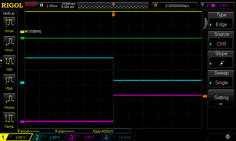
(spi_master.c) on the transmitting works very well but in the receiving it doesn't seem to work i tried to loop the tx part and on the oscilloscope everything works fine but when tried to loop the rx part the clock is not generated and the cs is always high 

i thought of trying the (soft_spi_master.c) and everything is correct on the tx and rx so what is the problem with hardware one 

note: i didn't modify the code at all just using a while(1) to watch the signals on the oscilloscope

thanks

  • Hi Samir,
    What do you mean you tried to "loop the rx part"? What is the hardware setup when you run the example? Do you have your MAX6675 connected to the MCU when running the example? The MCU is the master. Even in receive mode, the MCU must generate SPICLK. In order for the master to generate clock you still need to generate the dummy write on the MOSI even if you don't need to send data to the slave. The slave can ignore the transmitted data on the MOSI. But when the slave sees the SPICLK it will return the data on the MISO back to the master.
  • yes it's always connected using ssi0 pins (PA2-PA3-PA4) with 3.3v and GND
    by loop i meant that i had receiving for loop in the example in while (1) but strangely the receiving is now working when i used the none blocking function but now another strange thing is happening the max 6675 returns always the same value unless the i re upload the code and if the board is rested it doesn't give any output
  • Is the CS (SSI0FSS) pin active low during the transmission? Please show your scope cap and also your modified code.
  • //*****************************************************************************
    //
    // spi_master.c - Example demonstrating how to configure SSI0 in SPI master
    //                mode.
    //
    // Copyright (c) 2010-2017 Texas Instruments Incorporated.  All rights reserved.
    // Software License Agreement
    //
    //   Redistribution and use in source and binary forms, with or without
    //   modification, are permitted provided that the following conditions
    //   are met:
    //
    //   Redistributions of source code must retain the above copyright
    //   notice, this list of conditions and the following disclaimer.
    //
    //   Redistributions in binary form must reproduce the above copyright
    //   notice, this list of conditions and the following disclaimer in the
    //   documentation and/or other materials provided with the
    //   distribution.
    //
    //   Neither the name of Texas Instruments Incorporated nor the names of
    //   its contributors may be used to endorse or promote products derived
    //   from this software without specific prior written permission.
    //
    // THIS SOFTWARE IS PROVIDED BY THE COPYRIGHT HOLDERS AND CONTRIBUTORS
    // "AS IS" AND ANY EXPRESS OR IMPLIED WARRANTIES, INCLUDING, BUT NOT
    // LIMITED TO, THE IMPLIED WARRANTIES OF MERCHANTABILITY AND FITNESS FOR
    // A PARTICULAR PURPOSE ARE DISCLAIMED. IN NO EVENT SHALL THE COPYRIGHT
    // OWNER OR CONTRIBUTORS BE LIABLE FOR ANY DIRECT, INDIRECT, INCIDENTAL,
    // SPECIAL, EXEMPLARY, OR CONSEQUENTIAL DAMAGES (INCLUDING, BUT NOT
    // LIMITED TO, PROCUREMENT OF SUBSTITUTE GOODS OR SERVICES; LOSS OF USE,
    // DATA, OR PROFITS; OR BUSINESS INTERRUPTION) HOWEVER CAUSED AND ON ANY
    // THEORY OF LIABILITY, WHETHER IN CONTRACT, STRICT LIABILITY, OR TORT
    // (INCLUDING NEGLIGENCE OR OTHERWISE) ARISING IN ANY WAY OUT OF THE USE
    // OF THIS SOFTWARE, EVEN IF ADVISED OF THE POSSIBILITY OF SUCH DAMAGE.
    //
    // This is part of revision 2.1.4.178 of the Tiva Firmware Development Package.
    //
    //*****************************************************************************
    
    #include <stdbool.h>
    #include <stdint.h>
    #include "inc/hw_memmap.h"
    #include "driverlib/gpio.h"
    #include "driverlib/pin_map.h"
    #include "driverlib/ssi.h"
    #include "driverlib/sysctl.h"
    #include "driverlib/uart.h"
    #include "utils/uartstdio.h"
    #include "utils/uartstdio.c"
    
    //*****************************************************************************
    //
    //! \addtogroup ssi_examples_list
    //! <h1>SPI Master (spi_master)</h1>
    //!
    //! This example shows how to configure the SSI0 as SPI Master.  The code will
    //! send three characters on the master Tx then polls the receive FIFO until
    //! 3 characters are received on the master Rx.
    //!
    //! This example uses the following peripherals and I/O signals.  You must
    //! review these and change as needed for your own board:
    //! - SSI0 peripheral
    //! - GPIO Port A peripheral (for SSI0 pins)
    //! - SSI0Clk - PA2
    //! - SSI0Fss - PA3
    //! - SSI0Rx  - PA4
    //! - SSI0Tx  - PA5
    //!
    //! The following UART signals are configured only for displaying console
    //! messages for this example.  These are not required for operation of SSI0.
    //! - UART0 peripheral
    //! - GPIO Port A peripheral (for UART0 pins)
    //! - UART0RX - PA0
    //! - UART0TX - PA1
    //!
    //! This example uses the following interrupt handlers.  To use this example
    //! in your own application you must add these interrupt handlers to your
    //! vector table.
    //! - None.
    //
    //*****************************************************************************
    
    //*****************************************************************************
    //
    // Number of bytes to send and receive.
    //
    //*****************************************************************************
    #define NUM_SSI_DATA            3
    
    //*****************************************************************************
    //
    // This function sets up UART0 to be used for a console to display information
    // as the example is running.
    //
    //*****************************************************************************
    void
    InitConsole(void)
    {
        //
        // Enable GPIO port A which is used for UART0 pins.
        // TODO: change this to whichever GPIO port you are using.
        //
        SysCtlPeripheralEnable(SYSCTL_PERIPH_GPIOA);
    
        //
        // Configure the pin muxing for UART0 functions on port A0 and A1.
        // This step is not necessary if your part does not support pin muxing.
        // TODO: change this to select the port/pin you are using.
        //
        GPIOPinConfigure(GPIO_PA0_U0RX);
        GPIOPinConfigure(GPIO_PA1_U0TX);
    
        //
        // Enable UART0 so that we can configure the clock.
        //
        SysCtlPeripheralEnable(SYSCTL_PERIPH_UART0);
    
        //
        // Use the internal 16MHz oscillator as the UART clock source.
        //
        UARTClockSourceSet(UART0_BASE, UART_CLOCK_PIOSC);
    
        //
        // Select the alternate (UART) function for these pins.
        // TODO: change this to select the port/pin you are using.
        //
        GPIOPinTypeUART(GPIO_PORTA_BASE, GPIO_PIN_0 | GPIO_PIN_1);
    
        //
        // Initialize the UART for console I/O.
        //
        UARTStdioConfig(0, 115200, 16000000);
    }
    
    //*****************************************************************************
    //
    // Configure SSI0 in master Freescale (SPI) mode.  This example will send out
    // 3 bytes of data, then wait for 3 bytes of data to come in.  This will all be
    // done using the polling method.
    //
    //*****************************************************************************
    int
    main(void)
    {
    #if defined(TARGET_IS_TM4C129_RA0) ||                                         \
        defined(TARGET_IS_TM4C129_RA1) ||                                         \
        defined(TARGET_IS_TM4C129_RA2)
        uint32_t ui32SysClock;
    #endif
    
        uint32_t pui32DataTx[NUM_SSI_DATA];
        uint32_t pui32DataRx[NUM_SSI_DATA];
        uint32_t ui32Index;
    
        //
        // Set the clocking to run directly from the external crystal/oscillator.
        // TODO: The SYSCTL_XTAL_ value must be changed to match the value of the
        // crystal on your board.
        //
    #if defined(TARGET_IS_TM4C129_RA0) ||                                         \
        defined(TARGET_IS_TM4C129_RA1) ||                                         \
        defined(TARGET_IS_TM4C129_RA2)
        ui32SysClock = SysCtlClockFreqSet((SYSCTL_XTAL_25MHZ |
                                           SYSCTL_OSC_MAIN |
                                           SYSCTL_USE_OSC), 25000000);
    #else
        SysCtlClockSet(SYSCTL_SYSDIV_1 | SYSCTL_USE_OSC | SYSCTL_OSC_MAIN |
                       SYSCTL_XTAL_16MHZ);
    #endif
    
        //
        // Set up the serial console to use for displaying messages.  This is
        // just for this example program and is not needed for SSI operation.
        //
        InitConsole();
    
        //
        // Display the setup on the console.
        //
        UARTprintf("SSI ->\n");
        UARTprintf("  Mode: SPI\n");
        UARTprintf("  Data: 8-bit\n\n");
    
        //
        // The SSI0 peripheral must be enabled for use.
        //
        SysCtlPeripheralEnable(SYSCTL_PERIPH_SSI0);
    
        //
        // For this example SSI0 is used with PortA[5:2].  The actual port and pins
        // used may be different on your part, consult the data sheet for more
        // information.  GPIO port A needs to be enabled so these pins can be used.
        // TODO: change this to whichever GPIO port you are using.
        //
        SysCtlPeripheralEnable(SYSCTL_PERIPH_GPIOA);
    
        //
        // Configure the pin muxing for SSI0 functions on port A2, A3, A4, and A5.
        // This step is not necessary if your part does not support pin muxing.
        // TODO: change this to select the port/pin you are using.
        //
        GPIOPinConfigure(GPIO_PA2_SSI0CLK);
        GPIOPinConfigure(GPIO_PA3_SSI0FSS);
        GPIOPinConfigure(GPIO_PA4_SSI0RX);
        GPIOPinConfigure(GPIO_PA5_SSI0TX);
    
        //
        // Configure the GPIO settings for the SSI pins.  This function also gives
        // control of these pins to the SSI hardware.  Consult the data sheet to
        // see which functions are allocated per pin.
        // The pins are assigned as follows:
        //      PA5 - SSI0Tx
        //      PA4 - SSI0Rx
        //      PA3 - SSI0Fss
        //      PA2 - SSI0CLK
        // TODO: change this to select the port/pin you are using.
        //
        GPIOPinTypeSSI(GPIO_PORTA_BASE, GPIO_PIN_5 | GPIO_PIN_4 | GPIO_PIN_3 |
                       GPIO_PIN_2);
    
        //
        // Configure and enable the SSI port for SPI master mode.  Use SSI0,
        // system clock supply, idle clock level low and active low clock in
        // freescale SPI mode, master mode, 1MHz SSI frequency, and 8-bit data.
        // For SPI mode, you can set the polarity of the SSI clock when the SSI
        // unit is idle.  You can also configure what clock edge you want to
        // capture data on.  Please reference the datasheet for more information on
        // the different SPI modes.
        //
    #if defined(TARGET_IS_TM4C129_RA0) ||                                         \
        defined(TARGET_IS_TM4C129_RA1) ||                                         \
        defined(TARGET_IS_TM4C129_RA2)
        SSIConfigSetExpClk(SSI0_BASE, ui32SysClock, SSI_FRF_MOTO_MODE_0,
                           SSI_MODE_MASTER, 1000000, 8);
    #else
        SSIConfigSetExpClk(SSI0_BASE, SysCtlClockGet(), SSI_FRF_MOTO_MODE_1,
                           SSI_MODE_MASTER, 1000000, 16);
    #endif
    
        //
        // Enable the SSI0 module.
        //
        SSIEnable(SSI0_BASE);
    
        //
        // Read any residual data from the SSI port.  This makes sure the receive
        // FIFOs are empty, so we don't read any unwanted junk.  This is done here
        // because the SPI SSI mode is full-duplex, which allows you to send and
        // receive at the same time.  The SSIDataGetNonBlocking function returns
        // "true" when data was returned, and "false" when no data was returned.
        // The "non-blocking" function checks if there is any data in the receive
        // FIFO and does not "hang" if there isn't.
        //
        while(SSIDataGetNonBlocking(SSI0_BASE, &pui32DataRx[0]))
        {
        }
    
        //
        // Initialize the data to send.
        //
        pui32DataTx[0] = 's';
        pui32DataTx[1] = 'p';
        pui32DataTx[2] = 'i';
    
        //
        // Display indication that the SSI is transmitting data.
        //
    
        UARTprintf("Sent:\n  ");
    
        //
        // Send 3 bytes of data.
        //
    
            //
            // Display the data that SSI is transferring.
            //
    
    
            //
            // Send the data using the "blocking" put function.  This function
            // will wait until there is room in the send FIFO before returning.
            // This allows you to assure that all the data you send makes it into
            // the send FIFO.
            //
            SSIDataPut(SSI0_BASE, pui32DataTx[0]);
    
    
        //
        // Wait until SSI0 is done transferring all the data in the transmit FIFO.
        //
        while(SSIBusy(SSI0_BASE))
        {
        }
    
        //
        // Display indication that the SSI is receiving data.
        //
    
    
        //
        // Receive 3 bytes of data.
        //
      
    while(1){
         SysCtlDelay(200);
            //
            // Receive the data using the "blocking" Get function. This function
            // will wait until there is data in the receive FIFO before returning.
            //
         SSIDataPut(SSI0_BASE, &pui32DataRx[0]);
    
            //
            // Since we are using 8-bit data, mask off the MSB.
            //
         
            //
            // Display the data that SSI0 received.
            //
        }
    
        //
        // Return no errors
        //
    }
    

    those two images first one is after uploading the code the second one is after removing the usb and reconnecting it 

  • The SPICLK and CS looks proper. There is no MISO. The MISO comes from your MAX6675. Check if there is any drive conflict on the MISO. Unconnect the MISO from the MAX6675 to the MCU. Do you still see nothing on the MISO. If this is the case then you need to investigate on the MAX6675 side. Another thing to check is if you have proper voltage level on the SPICLK and CS. I can't tell from you scope cap.

    What if you don't unconnect the usb power but just reset the device?
  • if i did only a rest i get the first image but without a change in the readings if i unplugged the usb whatever i do i t doesn't work unless i re uplod the code
    when i disconnect the MISO i get the SPIclk and cs and nothing on the MISO
    i thought the problem is in the MAX side so i tested it with arduino and worked fine
    the voltages on the oscilloscope those images are taken in 2 v/div for the three channels
  • Please take scope capture of the CS and SPICLK right after you plug back the USB power. Perhaps your MAX device may have seen some switching activities on these two signal lines after the power up. Your MAX device does not know your MCU just came out of the power up. Any activities on the CS or SPICLK may confuse the MAX device into thinking it is a valid command. One more suggestion is to add a pullup on the CS signal and do you see any difference?
  • after adding PULL UP nothing new in all


    single shoot mode at the usb plugging 

  • Your delay inside the while(1) loop may be too short. You have a SysCtlDelay(200) which is much less than 0.17s. The MAX datasheet says the typical conversion time is 0.17s. If this is the case you are trying to read before the conversion is complete. Try to increase the delay (over 0.17s) and see if that makes a difference.
  • thanks Charles that solved my problem i don't know how i missed that :)
  • Glad your problem is solved.
  • Mr.Charles sorry but i did't notice this that i'm only getting the spi to work is through SSIDataPut if i didn't use it i still get no clock and the code doesn't work unless i use SSIDataPut  before SSIDataGet

    #include <stdbool.h>
    #include <stdint.h>
    #include "inc/hw_memmap.h"
    #include "driverlib/gpio.h"
    #include "driverlib/pin_map.h"
    #include "driverlib/ssi.h"
    #include "driverlib/ssi.c"
    #include "driverlib/sysctl.h"
    #include "driverlib/uart.h"
    #include "utils/uartstdio.h"
    #include "utils/uartstdio.c"
    
    
    int
    main(void)
    {
        uint32_t pui32DataRx;
        //
        SysCtlClockSet(SYSCTL_SYSDIV_1 | SYSCTL_USE_OSC | SYSCTL_OSC_MAIN | SYSCTL_XTAL_16MHZ);
    
        SysCtlPeripheralEnable(SYSCTL_PERIPH_SSI0);
        SysCtlPeripheralEnable(SYSCTL_PERIPH_GPIOA);
        GPIOPinConfigure(GPIO_PA2_SSI0CLK);
        GPIOPinConfigure(GPIO_PA3_SSI0FSS);
        GPIOPinConfigure(GPIO_PA4_SSI0RX);
        GPIOPinConfigure(GPIO_PA5_SSI0TX);
        //      PA5 - SSI0Tx PA4 - SSI0Rx PA3 - SSI0Fss PA2 - SSI0CLK
        GPIOPinTypeSSI(GPIO_PORTA_BASE, GPIO_PIN_5 | GPIO_PIN_4 | GPIO_PIN_3 | GPIO_PIN_2);
    
        SSIConfigSetExpClk(SSI0_BASE, SysCtlClockGet(), SSI_FRF_MOTO_MODE_1, SSI_MODE_MASTER, 1000000, 16);
        SSIEnable(SSI0_BASE);
    
        while(SSIDataGetNonBlocking(SSI0_BASE, &pui32DataRx))
        {
        }
    
    while(1){
         SysCtlDelay(20000000);
         SSIDataPut(SSI0_BASE, pui32DataRx); // without using this line the clock and cs doesn't work at all
         SSIDataGet(SSI0_BASE, &pui32DataRx);
    
        }
    }
    

    1) i also noticed that the SSI_SR register always have the value of 0x00000003 which tells that the SSI_SR_RNE is always zero 

    2) another thing to mintion that when ever i don't use the SSIDataPut before the SSIDataGet the code is alwyase trapped inside the internal while loop in the SSIDataGet function 

    thanks.

  • samir ibrahim said:
    ...only getting the spi to work via SSIDataPut  ...  get no clock and the code doesn't work unless SSIDataPut  occurs before SSIDataGet

    I'm sure friend Charles will agree - "SPI proivides, "Full Duplex communication" - Data is Sent on one clock edge - and (usually) Received on the other (clock edge.)

    What you are noting "IS NORMAL" - it is only the "SSIDataPut()" function which generates the SPI Clock!    

    The "SSIDataGet()" function simply "recovers that data received" - during the "immediately prior issued," "SSIDataPut()".    

  • The irony here is that my slave doesn't even require mosi
  • That (irony) is a great "choice of word" - yet (most) SPI slaves (certainly those more complex) do require clocked input data - and their response back to the master is (usually) one byte "behind."
  • does that mean that i can't receive unless i transmit ?
  • That is correct. You must generate dummy writes to the SPI master in order for the master to generate the SPICLK even the slave does not need the MOSI. The SSIDataGet() alone will not generate the SPICLK for you. This is inherent to the design. The SSIDataPut() writes the data into the SSIDR register and this is what trigger the SSI kernel to start the transmission (SPI clock generation). Please refer to my very first reply. I already mentioned you need dummy writes.