This thread has been locked.

If you have a related question, please click the "Ask a related question" button in the top right corner. The newly created question will be automatically linked to this question.

CC430F6137: UART erroneous communication

Part Number: CC430F6137
Other Parts Discussed in Thread: MSP-FET

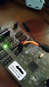
I have the MSP-FET USB programmer connected via JTAG to the EM-CC430F6137. I used this sample code for a basic UART test:

#include <cc430f6137.h>


/**
 * main.c
 */

void main(void)
{

	// Set UART (UCA0CTL0 & UCA0CTL1)

	//1. Always set the UCSWRST before setting the USCI module
	UCA0CTL1 |= UCSWRST;


	UCA0CTL1 |= UCSSEL_2;           // Use SMCLK as clock src

	// Set Baud rate
	UCA0BR0 = 9;                         // Low bit of UCBRx is 9
	UCA0BR1 = 0;                         // High bit of UCBRx is 0
	UCA0MCTL |= UCBRS_1 + UCBRS_0;       // Second stage modulation is 1 (9600 bauds)
	//UCA0STAT = UCLISTEN;                 // Enable internal loop-back


	//2. Clear UCSWRST
	UCA0CTL1 &= ~UCSWRST;                // Clear SW reset, resume operation

	//3. Enable UART TX & RX interrupts
	UCA0IE |= UCRXEIE | UCTXIE;

	_enable_interrupts();

	//LPM0;

}

// USCI A transmitter interrupt
#pragma vector=USCI_A0_VECTOR
__interrupt void USCIA0TX_ISR(void) {
                        
    switch(UCA0IV, 4) {
        case 0:break;
        case 2:
            while(!(UCA0IFG & UCTXIFG));        // Wait on the buffer
            UCA0TXBUF = UCA0RXBUF;
            break;
        case 4:break;
        default:break;
    }
}

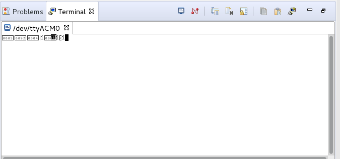
When I connect to the IDE's serial terminal I get back some strange output:

I figured, this must be coming from the debugger, because when I remove the JTAG cable from the EMCC430F6137 board I still get these results.

Another thing I've tried is to add these lines of code to the code above:

...

	
	P1DIR |= BIT6;                       // set P1.6 as TX
	P1SEL|= BIT5 + BIT6;           // select P1.5 & P1.6 to UART function
...

and then I tried using a TLL serial cable along with the *NIX program "screen" @ a baud-rate of 115200 (as shown in the picture below)

This second method doesn't work either. I get no output from the board.

What am I missing?

  • Hi Elude,
    the code as shown above does not make sense, as you're not looping in a code execution or stopping the CPU at the enable of interrupts, as in a lot of our examples. The code as is means after the enable of interrupts the CPU will continue with code execution but in a program memory space, where no code is present.
    I would recommend you using one of our tested UART code examples in the TI-Resource Explorer of the Code Composer Studio, which is downloadable for free, in case you you're not using it already anyway.
    There e.g. in the " cc430x613x_uscia0_uart_01.c" example you can see the halting of the CPU in LPM0 after UART and interrupt initialization.

    Best regards
    Peter
  • Hi Peter, thank you for taking the time to look over my code. The code above is literally the same from the file you suggested (with the exception of the LPM implementation - which has been commented out). I also went ahead and copied/pasted the content of your suggested file (ad litteram) into my main.c, but got the exact same result.

  • Hi Elude,
    I pointed you to the code example, to give you a reference on how to solve the problem with the CPU trying to execute code from non-initialized program memory. As described in the header of the code example and the other for CC430 for UART, these only transmit something on reception of a character. Not sure whether you're aware of that. So to see something from the CC430, you'd need to transmit at least one character to it.
    I'll modify the code to transmit permanently one character, without the need of reception.

    Best regards
    Peter
  • Hi Elude,
    I modified the code to permanent transmission of one and the same character in a while(1).
    This is one of the changes.
    The other change was to configure intentionally the clock system to run frm FLL and the 32kHz crystal as clock reference, as the integrated REFO can have x% deviation, which might corrupt the baud rate, and thus be one of the possible reasons for the malfunction.
    I have also changed the baud rate down to 9600, as I have no HW, where I could test the 115200 with the terminal in CCS. I used the G2xx Launchpad debugging section, which provides only 9600. With this, the code works fine.
    At this point also my request to check on your side, what kind of HW you're using for the UART back channel to PC, whether it is capable of running at 115200baud, as this might be also a part of the problems on your side.

    Best regards
    Peter

    #include <msp430.h>
    #include <stdint.h> // 01/04/2019

    char TXData = 0x55; // initialize TXData for // 01/04/2019
    // transmission of 'U's
    int main(void)
    {
    WDTCTL = WDTPW + WDTHOLD; // Stop WDT

    PMAPPWD = 0x02D52; // Get write-access to port mapping regs
    P1MAP5 = PM_UCA0RXD; // Map UCA0RXD output to P1.5
    P1MAP6 = PM_UCA0TXD; // Map UCA0TXD output to P1.6
    P2MAP7 = PM_SMCLK; // Map SMCLK to P2.7 // 01/04/2019
    PMAPPWD = 0; // Lock port mapping registers

    P1DIR |= BIT6; // Set P1.6 as TX output
    P1SEL |= BIT5 + BIT6; // Select P1.5 & P1.6 to UART function

    P2DIR |= BIT7; // switch P2.7 to output direction // 01/04/2019
    P2SEL |= BIT7; // select SMCLK function for P2.7 // 01/04/2019

    // Initialize LFXT1 // 01/04/2019
    P5SEL |= 0x03; // Select XT1 // 01/04/2019
    UCSCTL6 |= XCAP_3; // Internal load cap // 01/04/2018

    // Loop until XT1 fault flag is cleared // 01/04/2018
    do // // 01/04/2018
    {
    UCSCTL7 &= ~XT1LFOFFG; // Clear XT1 fault flags // 01/04/2018
    }while (UCSCTL7&XT1LFOFFG); // Test XT1 fault flag // 01/04/2018

    // Initialize DCO to 2.45MHz
    __bis_SR_register(SCG0); // Disable the FLL control loop // 01/04/2018
    UCSCTL0 = 0x0000; // Set lowest possible DCOx, MODx // 01/04/2018
    UCSCTL1 = DCORSEL_3; // Set RSELx for DCO = 4.9 MHz // 01/04/2018
    UCSCTL2 = FLLD_1 + 74; // Set DCO Multiplier for 2.4576MHz // 01/04/2018
    // (N + 1) * FLLRef = Fdco
    // (74 + 1) * 32768 = 2.4576MHz
    // Set FLL Div = fDCOCLK/2
    __bic_SR_register(SCG0); // Enable the FLL control loop // 01/04/2018


    UCA0CTL1 |= UCSWRST; // **Put state machine in reset**
    UCA0CTL1 |= UCSSEL_2; // SMCLK
    //UCA0BR0 = 9; // 1MHz 115200 (see User's Guide) // 01/04/2019
    //UCA0BR1 = 0; // 1MHz 115200 // 01/04/2019
    //UCA0BR0 = 21; // 2.4576MHz / 115200 // 01/04/2019
    //UCA0BR1 = 0; // // 01/04/2019
    UCA0BR0 = 0x00FF; // 2.4576MHz / 9600 // 01/04/2019
    UCA0BR1 = 0; // // 01/04/2019
    UCA0MCTL |= UCBRS_1 + UCBRF_0; // Modulation UCBRSx=1, UCBRFx=0
    UCA0CTL1 &= ~UCSWRST; // **Initialize USCI state machine**
    UCA0IE |= UCRXIE; // Enable USCI_A0 RX interrupt

    while (1) // main loop // 01/04/2019
    {
    while(!(UCA0IFG & UCTXIFG)); // wait until TX buffer ready for // 01/04/2019
    // next transmission
    UCA0TXBUF = TXData; // Load data onto buffer / transmit // 01/04/2019
    }
    // code never reached due to while(1) // 01/04/2019
    __bis_SR_register(LPM0_bits + GIE); // Enter LPM0, interrupts enabled
    __no_operation(); // For debugger
    }

    // Echo back RXed character, confirm TX buffer is ready first
    #if defined(__TI_COMPILER_VERSION__) || defined(__IAR_SYSTEMS_ICC__)
    #pragma vector=USCI_A0_VECTOR
    __interrupt void USCI_A0_ISR(void)
    #elif defined(__GNUC__)
    void __attribute__ ((interrupt(USCI_A0_VECTOR))) USCI_A0_ISR (void)
    #else
    #error Compiler not supported!
    #endif
    {
    switch(__even_in_range(UCA0IV,4))
    {
    case 0:break; // Vector 0 - no interrupt
    case 2: // Vector 2 - RXIFG
    while (!(UCA0IFG&UCTXIFG)); // USCI_A0 TX buffer ready?
    UCA0TXBUF = UCA0RXBUF; // TX -> RXed character
    break;
    case 4:break; // Vector 4 - TXIFG
    default: break;
    }
    }
  • Hi Elude,
    could you please give us an update on the status? Have you been able getting the communication up and running? Do you need further support? If not, please close the thread. Many thanks in advance.

    Best regards
    Peter
  • Hi Peter. Thanks for your reply. I have not been able to get the UART communication established (not even with the updated code). The cable and serial interface are linked in the initial post. I will assume that the TTL cable does not fit the required parameters for now. Please feel free to close this thread. Thanks much.
  • Hi Elude,
    many thanks for the clarification. I'll close the thread. In future, please click on "This resolved my issue" button. This gives us feedback and closes the thread automatically from your side.

    Best regards
    Peter