This thread has been locked.

If you have a related question, please click the "Ask a related question" button in the top right corner. The newly created question will be automatically linked to this question.

TM4C1230D5PM: TM4C1230 PC0 and PC1 port set to normal GPIO, program running error

Part Number: TM4C1230D5PM

Dear TI expert:

At present, when developing a new 3D printer, TM4C123X MUC is used as the main control chip, and some problems are encountered in the application process:
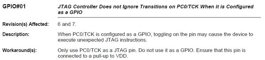
A. Pins 51 (PC1) and 52 (PC0) of the chip are used as common IO ports (PC0 and PC1 are TCK and TMS of JTAG). Due to insufficient chip resources, pins of JTAG are used as GPIO.
B. In the process of debugging, after the PC0 and PC1 repeatedly change state, a program is running the wrong case, show the other IO port output state is not correct, other input IO undetectable state changes, but PC0 and PC1 can detect port status changes, in this case the chip of USB communication available, PC can get the information of USB;
C. IO input adopts the query mode, and the timer is used to realize the cyclic timing query. USB adopts the method of interrupt receiving and sending after receiving the effective data.
D. The GPIOLOCK register has been set as 0X4C4F434B in the program, the GPIOCR register has been set, and the GPIO configuration program is the official routine of TI;
E. When setting system variables in the program, it can be seen that the program runs into functions that should not be called. It is not clear how to enter the system.
F. After PC0 and PC1 input a special timing sequence, the program can be restored to normal, and the status of other IO ports is normal, but it can be judged that the program is not reset and restarted, because USB can communicate all the time, and the communication has not been reconnected continuously;
G. If PC0 or PC1 is replaced with IO, the above phenomenon will not occur.

Please help to analyze the cause of the above situation,many thanks!!

  • Hi Hank,

     Sorry, your description is not clear to me. 

    • How are you using the PC0 and PC1? Are you using them as output or input? It seems like you want to use as input. Is this correct?
    • Are you saying once you re-purpose PC0 and PC1 as GPIO then your program will not run correctly? I'm not clear what you were saying. 
    • Are all units having the same issue you are describing? What is the percentage of your units having the issue?
    • It seems to me that you are using PC0 and PC1 to detect some type of input timing sequence. What if you use other pins in place of PC0 and PC1 to perform the same function? Will you see difference?
    • In your last comment you said if PC0 and PC1 are replaced with I/O then the issue does not happen? I don't understand what you mean. The PC0 and PC1 are already I/O. Do you mean if you use PC0 and PC1 as output then there is no issue? Only when you use PC0 and PC1 as input will you see issue?

  • Hi Charles,

    Described as follows.
    •How are you using the PC0 and PC1? Are you using them as output or input? It seems like you want to use as input. Is this correct?
    Yes,It's used as input;
    •Are you saying once you re-purpose PC0 and PC1 as GPIO then your program will not run correctly? I'm not clear what you were saying.
    Yes,When PC0 and PC1 are inputs and the state is changed repeatedly, the program will run incorrectly;
    •Are all units having the same issue you are describing? What is the percentage of your units having the issue?
    Yes,All units have the same problem;
    •It seems to me that you are using PC0 and PC1 to detect some type of input timing sequence. What if you use other pins in place of PC0 and PC1 to perform the same function? Will you see difference?
    Yes, it won't be a problem if you replace it with another pin
    •In your last comment you said if PC0 and PC1 are replaced with I/O then the issue does not happen? I don't understand what you mean. The PC0 and PC1 are already I/O. Do you mean if you use PC0 and PC1 as output then there is no issue? Only when you use PC0 and PC1 as input will you see issue?
    No,If PC0 and PC1 are replaced with other pins, there will be no problem;PC0 and PC1 is input.

    thanks a lot!!
  • Hi Hank,

     Thanks for he clarification. I think you might have hit the below errata. For experiment, if you don't use PC0 but still keep PC1, do you see any difference? The workaround for the errata is not to use PC0 for GPIO. 

  • Dear Charles
    Ok, thank you very much for your answer. Thank you