This thread has been locked.

If you have a related question, please click the "Ask a related question" button in the top right corner. The newly created question will be automatically linked to this question.

TM4C123BE6PZ: pin 13 (PE2/AIN1)

Part Number: TM4C123BE6PZ

Hi, I have an urgent matter with TM4C123BE6PZ!

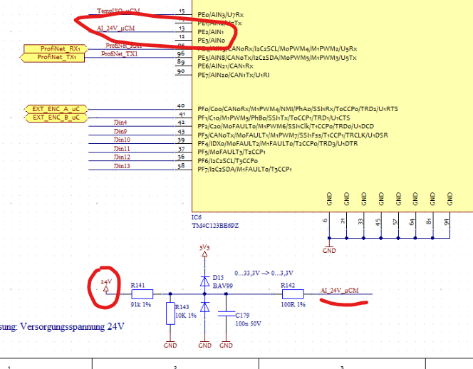
Our customer uses the analog input AIN2/PE2 to measure the 24V supply voltage of the whole board.
The 24V is divided with a 91K/10k voltage divider and protected with a 100n ceramic cap, a clamping Diode and a series 100R resistor in front of the pin.

See partial block diagram attached. 

The problem they have, is that when they turn on the main supply (24V) in some cases (maybe 1 of 50) the controller dies for any reason.

When they remove the 91k and no 24V are on the divider, then no failure happens!

Are there any known issues with this Port Pin?
Have you any guess what could be the problem?

Regards,

Jon

  • No known issues. Is the device Vdd powered on when the 24V is turned on? does turning on the 24V affect the level of Vdd or GND on the TM4C? When the TM4C "dies" what are the symptoms? Is the oscillator still running? Can they connect with JTAG?

  • Jon Bilbao said:
    Have you any guess what could be the problem?

    Guesses - this reporter's specialty.    Should the 24V supply (also) be supplying (through regulators) your '3V3 to the MCU'  (you do note that the 24V supplies voltage to the whole board) then is it not likely that the various capacitors - at/around the low voltage sections of your board - 'Delay the 3V3's arrival at the MCU?'

    Your '24V  input divider & protection circuit' looks fine - but for the 'too quick arrival' of the 10:1 voltage level.    You might consider adding circuitry to,

    • 'Close the 24V path (prior to R141)'  -  ONLY after the MCU's 3V3 is 'up & stable.'
    • 'Default switch the R141/R142 junction to ground, opening that ground connection (again) - ONLY after the MCU's 3V3 is 'up & stable.'

    Use of the MCU's gpio beckons - yet I fear may be too slow from 'Power On.'    There exist 'clever' circuits which provide (very) fast ATTACK - and then 'self-release' after a brief time.   (seconds or mS)

    Despite claims to the contrary - history rewards those who 'Only apply external signals to the MCU' - after it (MCU) is fully biased...

  • Thanks Bob,

    to answer your questions:

    • Is the device Vdd powered on when the 24V is turned on?

    No, the Vdd is generated from the 24V

    • does turning on the 24V affect the level of Vdd or GND on the TM4C?

    no

    • When the TM4C "dies" what are the symptoms? Is the oscillator still running? Can you connect with JTAG?

    The TM4C has no function, no oscillator is running and JTAG is not working

    Any guess to this problem?

    Thanks in advance!


    Best regards,
    Brian

  • First, let me say to CB1, it is great to have you back helping on the forum. Your experience and wisdom is greatly appreciated.

    It is possible that the 3.3V is delayed by the voltage regulator more than the 91K/100nF delays the voltage on PE2. I would expect D15 would prevent the voltage from getting very high on PE2 assuming that 3.3V is the same as what is on the Vdd pins. As an experiment, change the 100 Ohm R142 to 1K to see if that affects the fail rate. You might also post some scope shots showing the time relation of the rise of 24V and the rise of Vdd. I cannot say exactly what is happening, but as CB1 pointed out, strange things happen when the device starts to power-up through an I/O pin. I suspect it is affecting the internal power-on reset of the device. Are you using the external RST- pin?

  • Thank you for such kindness Bob - always appreciated.    My 'resurface' is brief though - and due to (several) 'forum-client' requests.

    Indeed your recognition of a 'properly managed MCU Reset circuit' proves helpful.

    May I amend your, 'Scope Caps' to include:

    • 24V rise vs. the MCU's VDD pin.     (MCU voltage should be delayed)
    • PE2's rise vs. MCU's VDD pin.       (Guaranteed that PE2 'beats' MCU's VDD arrival)   (playing w/'House Money' - only...)
    • PE2's rise vs. MCU's Reset pin.    (Expect PE2 to be 'up/stable' prior to MCU's 'Release from Reset.')    Clearly NOT Good!

    I would add that my firm's experience revealed, 'Highly similar (power disturbed) issues' - w/multiple (other brand) ARM Cortex MCUs!   It is highly doubted that such reveals (any) weakness w/your devices.   Instead - as mentioned - "Restraining signal inputs until the MCU's VDD is 'Up/Stable' - proves a (highly effective counter) to such (unwanted) & 'destructive issues.'

  • What is the status of this issue? 

  • HI Bob,

    sorry for delayed response!
    They are working on new prototypes with a new layout, where they also interposed an OPAmp. Unfortunately they didn´t make any measurements and for know I don´t have any updates here. So I think they are fine for now and will give me a feedback if there are any news.
    Thanks to you both for your inputs!

    Best regards,
    Brian