I have recently bought a BOOSTXL-SENSHUB and had interest in using its MPU-9150 with my EK-TM4C123GXL. The example available in CCS that makes use of the MPU-9150 works as intended, but it's a non-rtos example. I am planning to use the MPU-9150 for a TI-RTOS application.
The closest example to what I've wanted has been found in a zip file, in the following link: http://processors.wiki.ti.com/index.php/TI-RTOS_MPU9150
I have noticed that there are some differences in that example with how, for example, TI-RTOS GPIO driver is used to configure pin PB2 as input and to issue interrupts at falling edges. I am aware some changes must be made in order to use convenient MPU9150 APIs found in MPU9150.h.
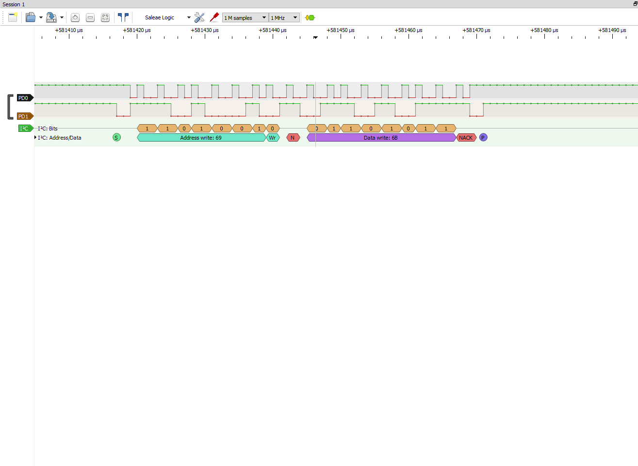
My current issue is that on my main, MPU9150_init() is returning false. I am not sure why, but I am thinking I need to do some changes to MPU9150.c, such as adding a transferMode, which seems absent from MPU9150.c found in the DK-TM4C123G TI-RTOS example. I have looked at the issue further and within MPU9150.c, the null is being returned due to I2C_transfer() returning false. I Will post parts of my code below, along with my project.
MPU9150_Handle MPU9150_init(unsigned int mpu9105Index,
                            unsigned int i2cIndex,
                            uint8_t i2cAddr)
{
    I2C_Params      i2cParams;
    I2C_Transaction i2cTransaction;
    Error_Block     eb;
    bool			transferOK;
    uint8_t		    writeBuffer[5];
    uint8_t		    readBuffer[1];
    MPU9150_Handle	handle = &object[mpu9105Index];

    /* Check if the handle was already opened */
    if((mpu9105Index > MPU9150_COUNT) || (handle->i2c != NULL)) {


    	return (NULL);
    }

    /*
     * Create GateMutex to guarantee that data received from the MPU9150
     * retains its coherency.
     */
    Error_init(&eb);
    handle->dataAccess = GateMutex_create(NULL, &eb);

    if (!handle->dataAccess) {


    	return (NULL);
    }


    /* Create I2C for usage */
    I2C_Params_init(&i2cParams);
    i2cParams.bitRate = I2C_400kHz;
    handle->i2c = I2C_open(i2cIndex, &i2cParams);
    handle->i2cAddr =  i2cAddr;

    /* If the I2C controller opened properly continue */
    if (handle->i2c) {

    	/* Used by all I2C transfers */
    	i2cTransaction.slaveAddress = i2cAddr;
    	i2cTransaction.writeBuf = writeBuffer;
    	i2cTransaction.readBuf = readBuffer;


    	/* Put the MPU9150 into reset state */
    	writeBuffer[0] = MPU9150_O_PWR_MGMT_1;
    	writeBuffer[1] = MPU9150_PWR_MGMT_1_DEVICE_RESET;
    	i2cTransaction.writeCount = 2;
		i2cTransaction.readCount = 0;

		//ISSUE is found in this if statement
       	if (!I2C_transfer(handle->i2c, &i2cTransaction)) {

            //added
            System_printf("I2C_transfer() returned false \n Closing program\n");
            System_flush();

			return (NULL);
		}

       	/*
		 * Check the value read back from status to determine if device
		 * is still in reset or if it is ready.  Reset state for this
		 * register is 0x40, which has sleep bit set. Device may also
		 * respond with an address NACK during very early stages of the
		 * its internal reset.  Keep polling until we verify device is
		 * ready.
		 */
       	writeBuffer[0] = MPU9150_O_PWR_MGMT_1;
       	i2cTransaction.writeCount = 1;
    	i2cTransaction.readCount = 1;
    	do {
    		transferOK = I2C_transfer(handle->i2c, &i2cTransaction);
    	} while ((readBuffer[0] != MPU9150_PWR_MGMT_1_SLEEP) || (!transferOK));

    	/* Take the device out of reset and enable the clock */
       	writeBuffer[0] = MPU9150_O_PWR_MGMT_1;
       	writeBuffer[1] = MPU9150_PWR_MGMT_1_CLKSEL_XG;
       	i2cTransaction.writeCount = 2;
    	i2cTransaction.readCount = 0;
       	if (!I2C_transfer(handle->i2c, &i2cTransaction)) {
			return (NULL);
		}

    	/* Enable A I2C Master mode on the MPU9150 */
       	writeBuffer[0] = MPU9150_O_USER_CTRL;
       	writeBuffer[1] = MPU9150_USER_CTRL_I2C_MST_EN;
       	i2cTransaction.writeCount = 2;
    	i2cTransaction.readCount = 0;
       	if (!I2C_transfer(handle->i2c, &i2cTransaction)) {


            //added


			return (NULL);
		}

       	/*
       	 * Change to power mode complete, device is ready for configuration.
       	 * Set MPU9150's sampling rate
       	 * Set sample rate to 50 hertz.  1000 hz / (1 + 19)
       	 */
       	writeBuffer[0] = MPU9150_O_SMPLRT_DIV;
       	writeBuffer[1] = 19;
       	i2cTransaction.writeCount = 2;
    	i2cTransaction.readCount = 0;
       	if (!I2C_transfer(handle->i2c, &i2cTransaction)) {


			return (NULL);
		}

       	/*
		 * Write the I2C Master delay control so we only sample the AK
		 * every 5th time that we sample accel/gyro.  Delay Count itself
		 * handled in next state.
		 */
       	writeBuffer[0] = MPU9150_O_I2C_MST_DELAY_CTRL;
       	writeBuffer[1] = (MPU9150_I2C_MST_DELAY_CTRL_I2C_SLV0_DLY_EN |
                          MPU9150_I2C_MST_DELAY_CTRL_I2C_SLV4_DLY_EN);
       	i2cTransaction.writeCount = 2;
    	i2cTransaction.readCount = 0;
       	if (!I2C_transfer(handle->i2c, &i2cTransaction)) {


			return (NULL);
		}

       	/*
		 * Write the configuration for I2C master control clock 400khz
		 * and wait for external sensor before asserting data ready
		 */
       	writeBuffer[0] = MPU9150_O_I2C_MST_CTRL;
		writeBuffer[1] = (MPU9150_I2C_MST_CTRL_I2C_MST_CLK_400 |
                          MPU9150_I2C_MST_CTRL_WAIT_FOR_ES);

		/*
		 * Configure I2C Slave 0 for read of AK8975 (I2C Address 0x0C)
		 * Start at AK8975 register status 1 (0x02)
		 */
		writeBuffer[2] = MPU9150_I2C_SLV0_ADDR_RW | 0x0C;
		writeBuffer[3] = 0x02;
		writeBuffer[4] = MPU9150_I2C_SLV0_CTRL_EN | 0x08;
       	i2cTransaction.writeCount = 5;
    	i2cTransaction.readCount = 0;
       	if (!I2C_transfer(handle->i2c, &i2cTransaction)) {


			return (NULL);
		}

       	/*
		 * Write the configuration for I2C Slave 4 transaction to AK8975
		 * 0x0c is the AK8975 address on i2c bus.
		 * we want to write the control register with the value for a
		 * starting a single measurement.
		 */
       	writeBuffer[0] = MPU9150_O_I2C_SLV4_ADDR;
		writeBuffer[1] = 0x0C;
		writeBuffer[2] = 0x0A; //AK8975_O_CNTL
		writeBuffer[3] = 0x01; //AK8975_CNTL_MODE_SINGLE
		writeBuffer[4] = MPU9150_I2C_SLV4_CTRL_EN | 0x04;
       	i2cTransaction.writeCount = 5;
    	i2cTransaction.readCount = 0;
       	if (!I2C_transfer(handle->i2c, &i2cTransaction)) {


			return (NULL);
		}

        /*
         * Write application specific sensor configuration such as filter
         * settings and sensor range settings.
         */
       	writeBuffer[0] = MPU9150_O_CONFIG;
    	writeBuffer[1] = MPU9150_CONFIG_DLPF_CFG_94_98;
		writeBuffer[2] = MPU9150_GYRO_CONFIG_FS_SEL_250;
		writeBuffer[3] = (MPU9150_ACCEL_CONFIG_ACCEL_HPF_5HZ |
                          MPU9150_ACCEL_CONFIG_AFS_SEL_2G);
       	i2cTransaction.writeCount = 4;
    	i2cTransaction.readCount = 0;
       	if (!I2C_transfer(handle->i2c, &i2cTransaction)) {
			return (NULL);
		}

       	/*
		 * Configure the data ready interrupt pin output of the MPU9150.
		 */
       	writeBuffer[0] = MPU9150_O_INT_PIN_CFG;
    	writeBuffer[1] = MPU9150_INT_PIN_CFG_INT_LEVEL |
                         MPU9150_INT_PIN_CFG_INT_RD_CLEAR |
                         MPU9150_INT_PIN_CFG_LATCH_INT_EN;;
		writeBuffer[2] = MPU9150_INT_ENABLE_DATA_RDY_EN;
       	i2cTransaction.writeCount = 3;
    	i2cTransaction.readCount = 0;
       	if (!I2C_transfer(handle->i2c, &i2cTransaction)) {


			return (NULL);
		}

    	return (handle);
    }
    else {


    	return (NULL);
    }
}