This thread has been locked.

If you have a related question, please click the "Ask a related question" button in the top right corner. The newly created question will be automatically linked to this question.

TMS470MF06607: CAN Communication Understanding

Part Number: TMS470MF06607
Other Parts Discussed in Thread: HALCOGEN

Hi all,

i am working on TMS470MF06607 and i have a OBD-II emulator. I have a 2 boards of TMS470 and both are working fine to each other with a CAN communication. 

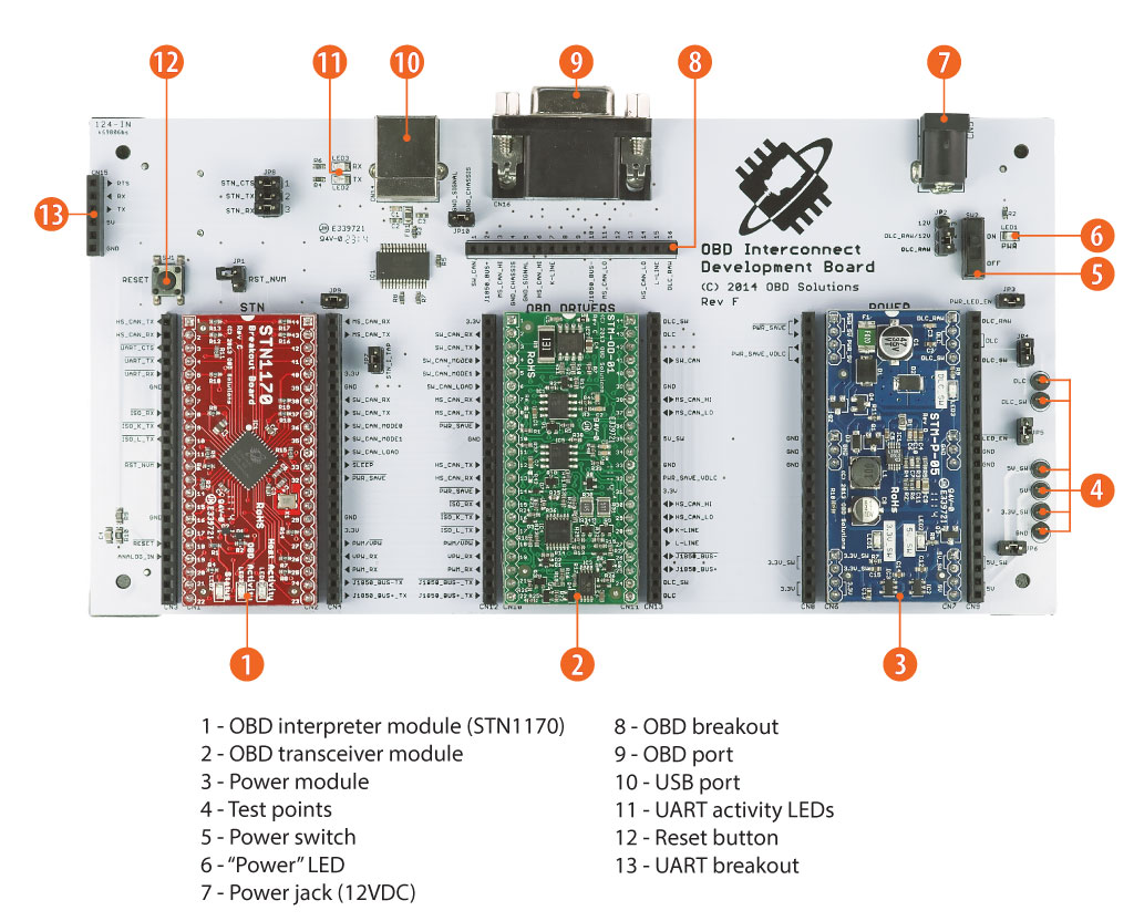
but i would like to test with OBD-II emulator, because its a standard tool i have to check real communication of CAN. 

but i don't know TMS470 is using High Speed CAN or Low Speed CAN, or K & L CAN or Medium speed CAN.

so, can anybody help me in this. how TMS is working and how can get a data from OBD-II board.

Thanks,

Anil D.

  • The baud rate of the CAN interface on the TMS470MF06607 is programmable. I assume by your question you did not write the software running on the TMS470MF06607 devices, or have access to the source code. Looking at the source is usually the best way to figure the baud rate and whether it uses 11 or 29 bit addresses. If this is not an option, capture the CAN communication between the two TMS470 devices on a logic analyzer or digital scope.

  • Hi Bob,

    actually for TMS470MF06607 ic i am using Halcogen for make a program for TMS program creating. so there on UI its not configurable to program that Identifier is 11 bit or 29 bit.

    how will i come to know about identifier in the frames.

    i will try with logical analyzer.

    Thanks

    Anil D.

  • Hi Bob,

    i tried with the config of CAN is like 250 bit rate with the mask of 0x1FFFFFFF,so it will work for 29 bit identifier, but still i am nor getting anything in my TMS code.

    https://e2e.ti.com/support/microcontrollers/hercules/f/312/t/477781?How-to-receive-29bit-ID-can-message-use-TMS570LS3137

    this link i studied, but still i am not getting.

    so i am checking on the DSO. i am checking like its differential signals so i have to check across MS_CAN_HI to MS_CAN_LOW pins or HS_PIN_HI and HS_PIN_LOW. because of differential ended results will be.

    but i am not seeing any changes in the signals.

    Thanks,

    Anil.

  • In the HALCoGen image you included, the baud rate was set to 500K baud. It is using 29 bit addressing because the "Enable Identifier Extension" box is checked.

  • Hi Bob,

    look at this settings. what i am doing now is i have a freematics and OBD-II STN2120 EVM board. Both i connected and i am trying to get a car speed, RPM of Engine. so on UART i am asking a question through EVM(STN2120) to Freematics so i am getting correct answers. 

    so i have 16 pin connector where i can see a MS_CAN_LOW & MS_CAN_High like wise HS_CAN_lOW & HS_CAN_High , J1850_BUS+ & J1850_BUS- , K-line & L-Line.

    so how i am checking now is while i am checking EVM to Freematics i am taping those 2 wires among them. but none of the combination i am getting result on my CAN controller.

    like for UART i can TAP a TX or RX and check a communication data. like wise i am trying to TAP and get a data on my controller. But not able to get a data.

    and while i am trying to check i am creating a such code according to freematics set protocol. for ex. if i set there as a CAN250kbps/11 bit then same type code i am loading in my controller.

    can you suggest me some another way to get a data. 

    for ex. CAN250kbps/11 bit this setting i set in Freematics then in the Halcogen i will set like 250kbps i will remove a tag from Enable identifier extension and in mask i will set as a 0x00007FF(which is 11bit identifier).

    and for 29 bit identifier i am setting a mask as a 0x1FFFFFFF. is everything correct? 

    Thanks,

    Anil.

  • For receiving any message, you want the mask bits to be all 0s. If the mask is all 1s, then only the message ID that matches the message ID number used to configure that mailbox will be saved.

  • Hi Bob,

    See this image, i have done a changes in a mask settings and i am trying to catch a data in between STN EVM and Freematics. Both are talking to each other. but nothing i am getting on my CAN.

    is there anything else i have to set for this.

    Because same protocol(250kbps/29bit) and even i make a mark in the extended identifier. and same code i developed by Halcogen also.

    Even though i tried with 0xFFFFFFFF mask value. But still i am not getting any results on my controller.

    i am not getting any kind of data.

    is there any another way to test a CAN data?

    i have DSO, but on DSO i am not able to recognize any changes in voltage of a lines.

    CAN Rx Code.txt
    Sample Code of CAN communication.
    
    
        canInit();
        sciInit();
        sciSetBaudrate(sciREG1, 115200);
        sciSend(sciREG1,strlen("Rx Program Started\n"),"Rx Program Started\n");
    
    
        while(1)
        {
        /*... wait until message receive on can1 */
        while(!canIsRxMessageArrived(canREG1, canMESSAGE_BOX1));
        canGetData(canREG1, canMESSAGE_BOX1, rx_data);  /* receive on can1  */
        sciSend(sciREG1,strlen("Rx_Data:"),"Rx_Data:");
        sciSend(sciREG1, strlen(rx_data), rx_data);
    
    	for(i=111111;i>0;i--);
         /* ... run forever */
        }

    See this attached coding for receiver i am loading.hanks,

    Anil D.

  • Anil Dhanawade said:
    i have DSO, but on DSO i am not able to recognize any changes in voltage of a lines.

    If you cannot see valid CAN signals with the oscilloscope, then that is likely why the TMS470 device is not seeing CAN messages. I would resolve that issue first before spending more time on the software. Look at CANH and CANL both with respect to ground. Both signals are at the same voltage during the recessive state (0 or idle) but CANH goes higher and CANL goes lower during the dominate state (1). 

    http://www.ti.com/lit/an/sloa101b/sloa101b.pdf

  • Hello Bob,

    I will clarify the Testing what i am doing.

    STN and Freematics  i have connected and i am sending question from STN to Freematics. so i am getting answer for that Question. mins both are talking to each other correctly.

    in middle i connected my TMS470MF06607 controller to catch a communication through line.  I think i can catch because multi master CAN will throw a data on CAN bus so everyone can catch that data. 

    my agenda to catch the same data.

    see on the 8th point you can see protocol names like HS_CAN_low/HS_CAN_HIGH and MS_CAN_HIGH/MS_CAN_LOW and K/L line etc. so i don't understand the 250kbps/11bit CAN controller will choose which protocol among these. 

    obd_interconnect_board.pdf

    on DSO i am checking like i have 2 wires which should connect to CAN HI pin or CAN low pin. so as per my knowledge its differential ended communication so i have to test across LOW and HIGH pin instead of testing in CAN HIGH and GND or CAN LOW and GND pin. but still i will check like CAN HIGH and GND pin while communication is happening. or in the CAN LOW and GND pin.

    Thanks Bob,

    Anil Dhanawade. 

  • Hi Bob, 

    I have done regress testing on boards and on DSO finally i have seen a data on a HS_CAN_HI and HS_CAN_LOW pins. so now i know data is being transferred from STN to Fremmatics and answer back.

    so there is no problem in the communication. but again a same thing in software how to receive a data?

    Thanks

    Anil D. 

  • From your scope picture you should be able to verify the baud rate. Just measure the width on the smallest pulse. It is likely a single bit in width. What hardware are you using for the TMS470? Have you verified on the scope that you are getting a signal through the CAN transceiver to pin 8 (if CAN1SRX) or pin 38 (if CAN2SRX)?

  • Hi Bob,

    See this image i verified that on pins i can see 250kbps if i set in freematics 250kbps/11bit, if i set 500kbps/11bit then i can see 500kbps on DSO also. there is no problem of data sending and receiving. 

    i am using TMS470MF06607 controller for catching a data in between. 

    i already told that if 2 TMS i connected and loaded a code into it then i can see a data TX and RX is happening. but i would like to catch a data so in that situation what i have to make changes in the coding?

    i think all changes we tried.

    Thanks,

    Anil Dhanawade.

  • Hi Bob,

    Today also i tried a lot many possible cases from hardware and software side.

    I tried with different board which is Sparkfun board. and i developed a code like 250kbps/29bit with 0x0000000 mask value.  so its start getting a result on TMS470MF06607 controller. i can catch a data on my controller and i can validate it.

    so happy so see data on CAN.

    huge support i got it from you to resolve or i can say got lot much of knowledge to judge a problem in different different ways.

    sincerely thanks,

    Anil Dhanawade.