This thread has been locked.

If you have a related question, please click the "Ask a related question" button in the top right corner. The newly created question will be automatically linked to this question.

TM4C123AH6PM: GPIO input signal behavior

Part Number: TM4C123AH6PM
Other Parts Discussed in Thread: TINA-TI

Hi Experts,

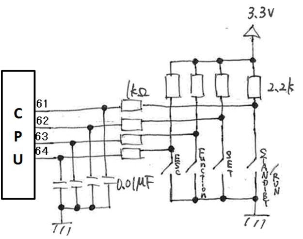
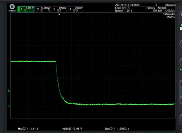
My customer is using below GPIO input circuit. Below is the TINA-TI simulation wave.

The input signal of above simulation data shows the tau is around 50us both for rising and falling. When the customer measures it, the time constant(tau) is hundreds nanoseconds and it is so fast transition.

The used ports are PD0, PD1, PD2 and PD3. These ports are set to input and internal PU and PD are disabled.

Do you have any idea what causes this fast transition?

Regards,

Uchikoshi

  • Hello Uchikoshi-san,

    I am not sure about how to go about simulation for the GPIO as I am not a designer for this device, but based on the datasheet specs, the simulated circuit must be wrong. The reason is simply that the datasheet specs the GPIO rise and fall times and they are in the ns range, not even in the hundreds range.

    Here is the full list of specs for that:

    As for what might be wrong with the Tina simulation, that is unfortunately beyond my knowledge to comment upon as I do not have the details about the exact circuits used in the design for the GPIO.

  • Ralph Jacobi said:
    The reason is simply that the datasheet specs the GPIO rise and fall times and they are in the ns range, not even in the hundreds range.

    The TINA-TI simulation screen capture appears to show a 10nF C1 between the GPIO pin and ground.

    Not sure if the TINA-TI simulation is using a different drive strength compared to the actual device, which may explain the difference in the GPIO rise and fall times.

  • Hi Jacobi,

    The spec you are referring to is the case that GPIO is set as output. Correct? This inquiry is the case for input mode.

    It is easy for me to do it by myself but due to COVID-19 I am redistricted to access to my lab.

    Generally, GPIO input pin is high impedance thus the tau is simply calculated that 10nF * 2K ohm = 20us. Do I misunderstand something?

    Regards,

    Uchikoshi

  • Hello Uchikoshi-san,

    From a simulation standpoint, I was asking around and the feedback I got is that we do not know if TINA has the correct models for TM4C. Instead the IBIS model we provide on the product page should be used for any simulation as this will provide accurate data on TM4C performance: https://www.ti.com/lit/zip/spmm873

    Regarding the GPI input pin, typically the internal input capacitance is very small. Usually in the range of a few pF (e.g. 5pF). If these capacitances are then in series, then the total capacitance would drop and it could explain the different from the actual performance vs the TINA simulation model.

  • Hi Jacobi,

    Please ignore the TINA-TI simulation result if this makes us confuse.

    Please look at below figure.

    I am expecting the slow rising and falling input signal of the order of 10us with this circuit when pressing and releasing the switch. But the actual waveform is below. It is very faster than exptected.

    note : 100ns/div

    Can you investigate what is wrong?

    Regards,

    Uchikoshi

  • Hello Uchikoshi-san,

    Based on the schematic you've presented here, we would not anticipate the MCU is responsible for causing this behavior... can you check on two points here:

    1) Verify the sizes of the capacitors and resistors that are populated to ensure they are actually the right values on the PCB.

    2) If they are are correct values, then disconnect the capacitor and 1kOhm series resistor from the GPIO and re-do the measurement to compare the results without them present in the system.