This thread has been locked.

If you have a related question, please click the "Ask a related question" button in the top right corner. The newly created question will be automatically linked to this question.

MSP432P401M: JTAG signals' connections

Part Number: MSP432P401M

Champs,

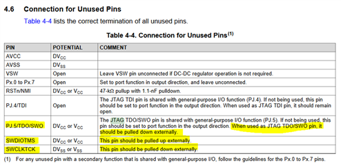
the https://www.ti.com/lit/an/slaa848/slaa848.pdf application report shows pull-up resistors on JTAG signals TMS and TCK and pull-down on TDO (e.g Fig 24, 25) but I do not see these resistors implemented on schematic pages of Launchpad or Experimenter board provided on the respective user guides. Could you please clarify what the best practices are wrt connection of these signals?

thank you

Michael

  • Hi Michael,

    According to the technical reference manual, sections 3.3.1.1 - 3.3.1.4, it appears all of these pins have internal pull up resistors enabled at POR by default.

    In the MSP432P401M datasheet, section 4.6 (table below), it shows that IF the TMS and TCK are not going to be used for JTAG, TMS should be pulled up externally, and TCK should be pulled down.

    If, however, 4-wire JTAG is used, it doesn't appear any external pull up/down resistors are needed.  I think this why the LaunchPads don't include these.

    Now, It does say, if using JTAG the TDO/SWO (output) pin should be pulled down.

    So that explains what you see in fig 24 and 25. The external pull up resistors are there reinforce the default internal pull up resistors (in case of noisy system) and the pull down on TDO is recommended. 

    Remember, what is shown in table 4-4 below are for "unused" pins, unless state otherwise.