Other Parts Discussed in Thread: TMS320F28335
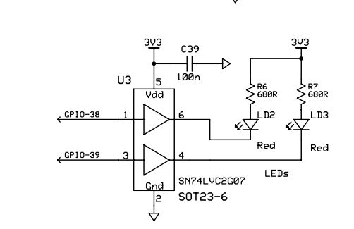
LEDBlink example is given in control suite TMS320F28335 library. It is actually meant for eZdsp in which GPIO32 is connected to LED. I have TMS320F28335 experiment kit. In that GPIO38 is connected to LED. I changed in code 32 to 38, but it is not blinking LED. It is working fine on GPIO32 of kit also(checked using external LED). Why it is not blinking LED connected to GPIO38?
#include "DSP2833x_Device.h"     // DSP2833x Headerfile Include File
#include "DSP2833x_Examples.h"   // DSP2833x Examples Include File

// Prototype statements for functions found within this file.
interrupt void cpu_timer0_isr(void);

void main(void)
{

// Step 1. Initialize System Control:
// PLL, WatchDog, enable Peripheral Clocks
// This example function is found in the DSP2833x_SysCtrl.c file.
   InitSysCtrl();

// Step 2. Initalize GPIO:
// This example function is found in the DSP2833x_Gpio.c file and
// illustrates how to set the GPIO to it's default state.
// InitGpio();  // Skipped for this example


// Step 3. Clear all interrupts and initialize PIE vector table:
// Disable CPU interrupts
   DINT;

// Initialize the PIE control registers to their default state.
// The default state is all PIE interrupts disabled and flags
// are cleared.
// This function is found in the DSP2833x_PieCtrl.c file.
   InitPieCtrl();

// Disable CPU interrupts and clear all CPU interrupt flags:
   IER = 0x0000;
   IFR = 0x0000;

// Initialize the PIE vector table with pointers to the shell Interrupt
// Service Routines (ISR).
// This will populate the entire table, even if the interrupt
// is not used in this example.  This is useful for debug purposes.
// The shell ISR routines are found in DSP2833x_DefaultIsr.c.
// This function is found in DSP2833x_PieVect.c.
   InitPieVectTable();

// Interrupts that are used in this example are re-mapped to
// ISR functions found within this file.
   EALLOW;  // This is needed to write to EALLOW protected registers
   PieVectTable.TINT0 = &cpu_timer0_isr;
   EDIS;    // This is needed to disable write to EALLOW protected registers

// Step 4. Initialize the Device Peripheral. This function can be
//         found in DSP2833x_CpuTimers.c
   InitCpuTimers();   // For this example, only initialize the Cpu Timers
#if (CPU_FRQ_150MHZ)
// Configure CPU-Timer 0 to interrupt every 500 milliseconds:
// 150MHz CPU Freq, 50 millisecond Period (in uSeconds)
   ConfigCpuTimer(&CpuTimer0, 150, 500000);
#endif
#if (CPU_FRQ_100MHZ)
// Configure CPU-Timer 0 to interrupt every 500 milliseconds:
// 100MHz CPU Freq, 50 millisecond Period (in uSeconds)
   ConfigCpuTimer(&CpuTimer0, 100, 500000);
#endif

// To ensure precise timing, use write-only instructions to write to the entire register. Therefore, if any
// of the configuration bits are changed in ConfigCpuTimer and InitCpuTimers (in DSP2833x_CpuTimers.h), the
// below settings must also be updated.

   CpuTimer0Regs.TCR.all = 0x4001; // Use write-only instruction to set TSS bit = 0

// Step 5. User specific code, enable interrupts:

// Configure GPIO32 as a GPIO output pin
   EALLOW;
   GpioCtrlRegs.GPBMUX1.bit.GPIO32 = 0;
   GpioCtrlRegs.GPBDIR.bit.GPIO32 = 1;
   EDIS;

// Enable CPU INT1 which is connected to CPU-Timer 0:
   IER |= M_INT1;

// Enable TINT0 in the PIE: Group 1 interrupt 7
   PieCtrlRegs.PIEIER1.bit.INTx7 = 1;

// Enable global Interrupts and higher priority real-time debug events:
   EINT;   // Enable Global interrupt INTM
   ERTM;   // Enable Global realtime interrupt DBGM

// Step 6. IDLE loop. Just sit and loop forever (optional):
   for(;;);
}


interrupt void cpu_timer0_isr(void)
{
   CpuTimer0.InterruptCount++;
   GpioDataRegs.GPBTOGGLE.bit.GPIO32 = 1; // Toggle GPIO32 once per 500 milliseconds
   // Acknowledge this interrupt to receive more interrupts from group 1
   PieCtrlRegs.PIEACK.all = PIEACK_GROUP1;
}