Hi,
The following question describes a problem I faced and the investigation that lead me to a workaround. I wish to know if my reasoning is correct and if the workaround will be future proof.
My design uses all 12 EPWM of my DSP. It's configured in 2 groups with one master each that generates a sync signal. PWM1 sync to PWM2 to 6, PWM7 is the master of PWM 8 to 12. All slave has their phase control enabled (PHSEN=1). To get this configuration, SYNCSELEPWM10SYNCIN = 2
I recently started to witness some units failing in a strange pattern whereas the design have been stable for years now. In a random-looking pattern, PWM11 or PWM12 output would make a long pulse. My CPU is running at 200Mhz, TBPRD=1110, working in up-down mode giving a square wave output of 90KHz with a steady 50% duty cycle. Quite often, the output will "skip a pulse" giving one pulse of 150%.
After investigation, I gathered all of these facts
- This would only happen on PWM11 & PWM12
- Failing pattern only happens in the following conditions (others value tested and behaviour is stable)
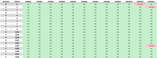
- Direction is DOWN (PHSDIR=0) and phase value is 0 or 1 (TBPHS=0,1)
- Direciton is UP (PHSDIR=1) and phase is 1110 (TBPHS=TBPRD).
- The failure is independent of how the CPMA,CMPB, TBPHS register of other PWM module are configured.
- All failing units have the same DSP batchcode : YFC-94A9RPW
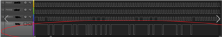
Pushing the investigation further, I started to monitor the behavior of the counter when the problem occured. What I saw was 2 type of failure mode
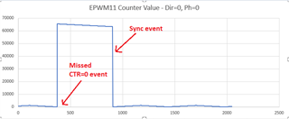
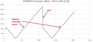
1. The up-down mode seemed to miss a CTR=0 or CTR=PRD event and would continue counting out of the bounds [0-1110] until the next sync event.

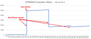
2. The second failure mode is more troubling. Upon a sync event, the phase value loaded in the TBCTR register seemed to be random-like. Remember that the counter is supposed to stay within 0 and 1110.
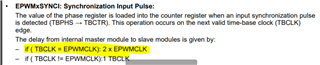
Looking into the manual I found this statement
Conclusion
With all the above statements, I am feeling like there is some kind of race-condition in the timer module.
Like if the timebase module would invert the counting direction from DOWN to UP when hitting 0, but the sync event would then rechange the direction back to DOWN without having the timebase module reacting a 2nd time and the timer would keep going in the negative (65535 and below). Assuming this would be the case, I can easily saturate my phase register depending on the direction between [2. 1108].
This solutions does fix all the problems, but I cannot explain the 2nd failure mode with that reasoning which leaves me doubtfull about the solution I am using. It would make sense if I was in front of a real hardware asynchronous race-condition, but since I am dealing with a synchronous design, I can't explain the "random-like" phase reload value. But the fact that is tied to a single batch of chip let me think that maybe its an asynchronous race-condition.
I would need the help from TI here to assess what would be the correct approach to deal with this situation.
Thank you very much