

Other Parts Discussed in Thread: DRV8301
Dear team:
A customer of mine has the following problems after comparing the routines "HVBLDC_Sensorless①" and "InstaSPIN-BLDC②":
1、For PWM output, there are the same test result waveforms in the two routines:
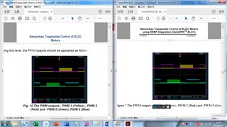
However, judging from the state1 codes of the two, the PWM waveforms of the two sides should be obviously different:
①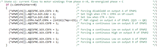
②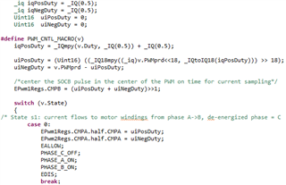
It can be seen that PWM1A, PWM1B, PWM2A, and PWM2B will all output PWM waves, and PWM2B will not be forced high in this state like the HVBLDC_Sensorless routine.
Is the waveform of the PWM wave oscilloscope in the InstaSPIN-BLDC routine wrong?
2、According to the code of InstaSPIN-BLDC state1, he understood the PWM wave output mode of the project as shown in the figure below:
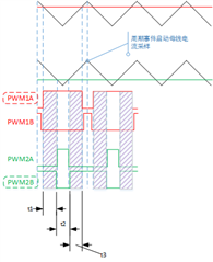
As shown in the figure, at t1 and t3, PWM1A and PWM2B are both high at the same time, and the conduction relationship and current path are as follows:
However, at t2, there should be no current path. Will this be a problem? Then again, if a periodic event triggers AD sampling, how to collect the bus current? From the waveform analysis chart, there should be no continuous current at the periodic point?
3、What is the principle of PWM output in the InstaSPIN-BLDC routine?
