Other Parts Discussed in Thread: C2000WARE
Hello,
I am having a hard time ensuring I am going to put the correct values inside the different counter/seed registers.
So I'll expose to you my use cases so that you can help me figuring it out.
First use case
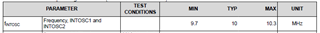
I want to monitor the external 20MHz 50ppm crystal connected on X1 (clock source 0) using INTOSC1 (clock source 1).
Second use case
I want to monitor the external 20MHz 50ppm crystal connected on X1 (clock source 0) using INTOSC1 (clock source 1).
Third use case
I want to monitor an external 1MHz 50ppm crystal connected on a GPIO and redirected on the Input X-BAR input 15 (clock source 1 of the DCC) using INTOSC1 (clock source 0).
Fourth use case
I want to monitor an external 1MHz 50ppm crystal connected on a GPIO and redirected on the Input X-BAR input 16 (clock source 0 of the DCC) using INTOSC0 (clock source 1).
For all four cases, my end goal is to perform a 1% tolerance monitoring of the crystals frequencies (more than the 50ppm but we don't need a very close monitoring).
Can you please help me out and in particular guide me for each case on the computation of the different steps:
- DCC error
- Window
- Frequency error allowed
- Total error
- Counter0
- Valid0
- Counter1
Thank you,
Best regards
Clément