This thread has been locked.

If you have a related question, please click the "Ask a related question" button in the top right corner. The newly created question will be automatically linked to this question.

TMS320F28379D: Glitch appearing after configuring glitch filter (input qualifier)

Part Number: TMS320F28379D

Hello,

We are having some issues with the "Input qualifier" feature of the GPIO module. The microcontroller is receiving a bad signal (pulse) after the input qualifier is configured. This, for example, makes the MCU trigger an interrupt.

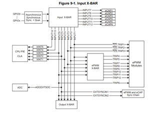
We confirmed that a fake signal transition is generated after activating the input qualifier. We configure a XBAR from that input to another pìn (assuming that the XBAR input is connected after the input qualifier). We see a pulse at the output of the XBAR, but it does not correspond with the value that we input to the pin.

The next image shows the issue, the yellow signal is the real input value (input pin of the MCU), and the blue signal is the output of the XBAR. The blue signal has a 

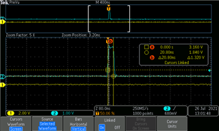
This is specially problematic with the "encoder index input" of the eQEP peripheral. When we configure the glitch filter to be active (qualification with 3 samples), a index pulse is received. But in this case, the eQEP module does not trigger the index event ISR automatically, it waits until A or B transition is received (we use QEPCTL[IEL] = 3). Due to that we cannot filter that interrupt on an easy way. 

Is this a known issue? Could you give me a workaround to bypass the issue?

Thank you and regards,

Rodrigo.

  • Rodrigo,

    I'm a bit confused. Are you saying that the qualification of 3 cycles does NOT filter out the pulse?

    Nima

  • Hi,

    No, I'm saying that the qualification is creating a pulse.

    The yellow signal is the "encoder index" input. The blue signal is the internal value of the "encoder index" input, after the qualification block. That pulse is triggering the ISR. 

    This only appears while the MCU is configuring the input qualification registers.

    Rodrigo.

  • Rodrigo,

    I have never seen this before. Let me see if anyone else has seen this before.

    Nima

  • This is a configuration issue. Can you show some block diagrams of your configuration?

  • Hi Nima,

    See attached a part of the code that we are using. The EQEPStart function is called during MCU initialization, inside this function, we call EQEPConfigureInputs, which configures the GPIOs and the glitch filter.

    #define GPIO_SYNC          (0x0 << 4)
    #define GPIO_QUAL3         (0x1 << 4)
    
    /** This function is called in eQEP initialization function. */
    void EQEPConfigureInputs(const TQepIntf* ptInst, uint16_t u16Level)
    {
        if (ptInst != NULL)
        {
            uint32_t u32GpioFlags;
            /* Update prescaler */
            if (u16Level == GLITCH_FILTER_DISABLED)
            {
                u32GpioFlags = (uint32_t)GPIO_SYNC;
            }
            else if (u16Level <= GLITCH_FILTER_PRESCALER_LEVELS)
            {
                u32GpioFlags = (uint32_t)GPIO_QUAL3;
                /** Filter level selects different filter configurations (prescaler). */
                GpioCtrlRegs.GPDCTRL.bit.QUALPRD0 = u16FilterPresc[u16Level-1];
            }
    
            EALLOW;
            /** Configure the EQEP1 A B and index inputs. */
            GPIO_SetupPinOptions(EQEP_1_A_PIN, GPIO_INPUT, u32GpioFlags);
            GPIO_SetupPinMux(EQEP_1_A_PIN, EQEP_1_CPU, EQEP_1_A_PIN_MAP);
    
            GPIO_SetupPinOptions(EQEP_1_B_PIN, GPIO_INPUT, u32GpioFlags);
            GPIO_SetupPinMux(EQEP_1_B_PIN, EQEP_1_CPU, EQEP_1_B_PIN_MAP);
    
            GPIO_SetupPinOptions(EQEP_1_I_PIN, GPIO_INPUT, u32GpioFlags);
            GPIO_SetupPinMux(EQEP_1_I_PIN, EQEP_1_CPU, EQEP_1_I_PIN_MAP);
            EDIS;
        }
    }
    
    void EQEPStart(TQepIntf* ptInst, const TQepCfg* ptCfg)
    {
        if (ptInst != NULL)
        {
            /* Disable index interrupt */
            HND_REGISTER->QEINT.bit.IEL = (uint16_t)0U;
    
            /* eQEP GPI Init */
    #if defined(CPU1)
            if (ptCfg->u16FltrLvl != HND_ACCESS.tCfg.u16FltrLvl)
            {
                /* Disable module before reconfiguring inputs to avoid rogue interrupts */
                HND_REGISTER->QEPCTL.bit.QPEN = (uint16_t)0U;
                /* Configure Encoder's inputs and Glitch Filter's prescaler */
                EQEPConfigureInputs(ptInst,  ptCfg->u16FltrLvl);
            }
    #endif
    
            /* Configure the decoder for quadrature count mode */
            /* eQEP Quadrature-clock inputs are swapped depending on polarity */
            EQEPSetPolarity(ptInst, ptCfg->u16Polarity);
    
            /* eQEP External clock rate is 1x Resolution (count only rising and falling edges) */
            HND_REGISTER->QDECCTL.bit.XCR = (uint16_t)1U;
    
            /* eQEP Quadrature count mode */
            HND_REGISTER->QDECCTL.bit.QSRC = (uint16_t)0U;
    
            /* eQEP Position counter stops immediately on emulation suspend */
            HND_REGISTER->QEPCTL.bit.FREE_SOFT = (uint16_t)0U;
    
            /* eQEP Position counter reset on the maximum position */
            HND_REGISTER->QEPCTL.bit.PCRM = (uint16_t)1U;
    
            /* Set eQEP maximum position to maximum uint32 */
            HND_REGISTER->QPOSMAX = (uint32_t)0xFFFFFFFFUL;
    
            /* Set period of eQep unit timer: (SYSCLKOUT/UpdateFreq) - 1 */
            EQEPSetPosLatchFreq(ptInst, ptCfg->u32UpdateFreq);
            HND_REGISTER->QUPRD = ((uint32_t)SYSTEM_FREQ_HZ/
                    tHandler[ptInst->ptPriv->u16Id].tCfg.u32UpdateFreq) - (uint32_t)1UL;
    
            /* Initialize eQep timer to 0 */
            HND_REGISTER->QUTMR = (uint32_t)0UL;
    
            /* Position counter, capture timer and capture period are latched on unit time out */
            HND_REGISTER->QEPCTL.bit.QCLM = (uint16_t)1U;
    
            /* Enable peripheral unit timer */
            HND_REGISTER->QEPCTL.bit.UTE = (uint16_t)1U;
    
            /* Latch position with index pulse on index event marker */
            HND_REGISTER->QEPCTL.bit.IEL = (uint16_t)3U;
    
            /* Dont latch position with strobe signal */
            HND_REGISTER->QEPCTL.bit.SEL = (uint16_t)0U;
    
            /* Clear index interrupt flag */
            HND_REGISTER->QCLR.all = IEL_INT_CLR_MASK;
    
            /* Enable index interrupt */
            HND_REGISTER->QEINT.bit.IEL = (uint16_t)1U;
    
            switch (ptInst->ptPriv->u16Id)
            {
                case EQEP_INSTANCE_1:
                    IntEnable(EQEP_1_INT_SRC);
                    break;
    
                case EQEP_INSTANCE_2:
                    IntEnable(EQEP_2_INT_SRC);
                    break;
    
                default:
                    /* Nothing */
                    break;
            }
    
            /* Enable Module */
            HND_REGISTER->QEPCTL.bit.QPEN = (uint16_t)1U;
        }
    }
    

    After the eQEP module is initialized, if we move the encoder, at the first A/B count that the eQEP receives the index event interrupt is triggered (bad behavior). This only happens when we activate the glitch filter with GPIO_QUAL3. If we don't activate the qualifier, the index event interrupt is not called until the MCU receives a pulse on the eQEP index input (expected behavior).

    (GPIO_SetupPinOptions function is available in F2837xD_Gpio.c)

    Regarding the scope image that I posted, the yellow and blue signal of the plot are taken from here:

    In the blue output we see a pulse that does not appear on the yellow input. The block diagram of the configuration was made taking into account the next diagram from the TMS reference manual: 

    We need a way to avoid triggering the index event ISR when we configure the qualifier. I suppose that this can be achieved by two ways, the first should be to apply a workaround in the eQEP initialization (please check if there is something wrong on it). The second solution is to find a way to not generate a pulse in the input (after qualification block). 

    For me the last solution would be the good one, so the problem will be fixed from the root.

    Thank you and regards,

    Rodrigo.

  • Do you have anything else enabled in the OUTPUT XBAR?

  • No. The XBAR is exclusivelly used for monitoring that signal, also, the pin is not used with other purpose.

    Rodrigo.

  • We need a way to avoid triggering the index event ISR when we configure the qualifier. I suppose that this can be achieved by two ways, the first should be to apply a workaround in the eQEP initialization (please check if there is something wrong on it). The second solution is to find a way to not generate a pulse in the input (after qualification block). 

    Rodrigo,

    The pulse should not be happening when the qualification is enabled. Lets ignore the EQEP for this debug. The issue is that GPIO Input, going through QUALIFICATION is causing this pulse on the GPIO out.

    To speed this up, can you create a SMALL CCS project with the pinmux configuration and the OUTPUT XBAR configuration that recreates generating this first abnormal pulse? I can review this on my scope and provide you the solution.

    The only thing that comes into mind is the order of setting the registers. 

    Send me a CCS project with only:

    • PinMux initialization
    • XBAR initialization
    • GPIO Qualification

    That recreates the issue.

    Nima

  • Hi Nima,

    We cannot reproduce the issue anymore if we create a new project with only the XBAR and the input qualification block. We will continue integrating the eQEP and see if the issue still appears then. 

    Thank you,

    Rodrigo.

  • Hi,

    Finally we found a workaround for this issue. It seems that the problem was the initialization routine of the eQEP module. 

    The workaround for that issue is this one:

    1. Set the QEPCTL[IEL] to '0'
    2. Unsubscribe the ISR callback for the eQEP index event.
    3. Set to '0' the QEPCTL[QPEN] bit.
    4. Configure the eQEP inputs.
    5. Enable the interrupt by QEINT[IEL]

    After this, we continue configuring eQEP, and before finishing the configuration, we subscribe again the ISR callback and set QEPCTL[IEL] to 3.

    If we don't follow this procedure, a index event ISR is triggered after the first A/B level change. For what we saw during our investigations it may not be related to the eQEP index input signal (or qualification block). 

    Thank you and regards,

    Rodrigo.

  • Is it possible that an index event is latched after setting QEPCTL[IEL] = 3?

  • I am adding the EQEP expert to help with this! can you help with this?

  • Hi Rodrigo,

    Why do you set QEPCTL[IEL]=3? This is a SW index marker, and will latch First index marker following the index signal. Basically it will emulate first index event.

    Best Regards,

    Nirav

  • Hi Nirav,

    We used IEL=3 to obtain the direction at the index moment, latched in QEPSTS[QDLF] register. 

    I re-checked it in the reference manual but it is a bit confusing.

    In the case that you are saying, we don't need to emulate the index, so we will continue using IEL=1.

    Thank you and regards,

    Rodrigo.

  • Hi Rodrigo - I will take an action to clarify this better in our TRM. I will go ahead and close this thread, let us know if you have any more questions.

    Best Regards,

    Nirav