This thread has been locked.

If you have a related question, please click the "Ask a related question" button in the top right corner. The newly created question will be automatically linked to this question.

TMS320F28379D: TMS320F28379D ADC EPWM example

Part Number: TMS320F28379D
Other Parts Discussed in Thread: LAUNCHXL-F28379D, TMDSCNCD28379D, C2000WARE

Dear TI.

I want to do ADC using TMS320F28379D.

My final goal is motor control.

So I want to make interrupt using EPWM for ADC.

I opened the adc_soc_epwm ex02.

But, it runed one time .

How can I do it continuously?


Best regards,

Mingi Oh

  • Mingi,

    Is the execution halting on the ESTOP0 instruction? If so, please follow the directions in the comments:

    You may also remove the ESTOP0 instruction and rebuild the project to allow the ADC triggers to be generated continuously.

    -Tommy

  • Thank you.

    And Can I ask one more thing.

    I want to see the ADC result in the CCS.

    So I set the value like below.


    and when I saw the value, it looks weird.

    There is big spike as you can see.

    The input value is 60Hz 1Vpp voltage.

    Can you give me a some sugeestion?

    and also when I looked at the butter the number is not the exact number as what I input.

    I think I should some transformation.

    What equation should I need to use?

    Best regards,

    Mingi Oh

  • There is big spike as you can see.

    The C28x is a 16-bit addressible CPU so you will want to change the Dsp Data Type to 16 bit unsigned integer.

    The input value is 60Hz 1Vpp voltage.

    Can you give me a some sugeestion?

    and also when I looked at the butter the number is not the exact number as what I input.

    I think I should some transformation.

    What equation should I need to use?

    You can refer to the TRM guidelines:

  • Thank you for the information.

    But I am still struggling with this issue

    The below graph is my adc buffer output.

    It does not look like sine wave form.

    I just connected 1Vpp to J30.

    Did I miss something?

    Also, I have some additional questions about this ADC.

    1. When I connected PinJ3 GND to 1Vpp input ground and measure voltage in oscilloscope, the waveform is not sinewave anymore.

    What is the reason for it?

    I do not have to connect GND in the launch pad from externally when I use ADC module?

    2. Vreflo and VrefHI

    You explained if I want to transfer to the real value, I need to calculate the value using Vreflo and VrefHi.

    And when I studied about it, it lookes likes external value.

    Can I conned 5V or 3.3V for VrefHi and GND for the VrefLo in the launchpad?

    Thank you for always your help.

    Best regards,

    Mingi Oh

  • I just connected 1Vpp to J30.

    Did I miss something?

    I recommend that you first try to sample DC voltage levels to gain confidence in the ADC behavior before moving on to AC signals.

    1. When I connected PinJ3 GND to 1Vpp input ground and measure voltage in oscilloscope, the waveform is not sinewave anymore.

    What is the reason for it?

    I do not have enough information to provide an explanation for what is going on in your system. It would make sense to correct the observable input signal before trying to interpret the ADC conversions.

    I do not have to connect GND in the launch pad from externally when I use ADC module?

    A ground reference is definitely required for all input signals.

    2. Vreflo and VrefHI

    You explained if I want to transfer to the real value, I need to calculate the value using Vreflo and VrefHi.

    And when I studied about it, it lookes likes external value.

    Correct, the reference voltages are external to the F28379D. TI EVMs like LAUNCHXL-F28379D and TMDSCNCD28379D include on-board references already. You can find additional details in the relevant schematics.

    Can I conned 5V or 3.3V for VrefHi and GND for the VrefLo in the launchpad?

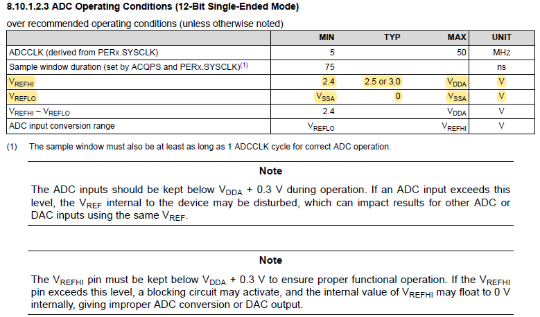
    Any reference voltage level that satisfies the datasheet requirements may be used:

    The TRM provides guidelines for Designing an External Reference Circuit.

  • Dear tlee,

    Thank you for explain,

    I have a question about the one of the answer. 

    2. Vreflo and VrefHI

    You explained if I want to transfer to the real value, I need to calculate the value using Vreflo and VrefHi.

    And when I studied about it, it lookes likes external value.

    Correct, the reference voltages are external to the F28379D. TI EVMs like LAUNCHXL-F28379D and TMDSCNCD28379D include on-board references already. You can find additional details in the relevant schematics.

     I can find the Vreflo(PIn33) and Vrefhi(Pin37) of the F28379D.

    However, I don't know how I can access the Pin in the lauchpad.

    When I looked at the datasheet of the launchpad, there are not connected the Vreflo and Vrefhi..

    Could you please let me know how to connect those pins using Launchpad?

    Best regards,

    Mingi Oh

  • Mingi Oh,

    The ADC VREF pins are not routed to the LaunchPad headers because on-board reference circuitry is already installed. You can find the schematic snippet in the User's Guide or the full PDF in C2000Ware:

    ~\C2000Ware_XXXX\boards\LaunchPads\LAUNCHXL-F28379D\R2.0

    -Tommy

  • Thank you for the reply.

    So I don't need to connect Vreflo and Vrefhi.

    Therefore, when I run the explample2, I need only to connect analog input to J30, right?

    I don't need any other connection, right?

    Best regards,

    Mingi Oh

  • Yes, an input signal and a common ground reference should suffice.