This thread has been locked.

If you have a related question, please click the "Ask a related question" button in the top right corner. The newly created question will be automatically linked to this question.

TMDSCNCD28335: resolver to digital conversion for high speeds

Part Number: TMDSCNCD28335
Other Parts Discussed in Thread: TMS320F28379D, CONTROLSUITE

I am using TMDSCNCD28335 for high speed machine control application. The speed needs to be sensed through a resolver (Part no. RO2010, Datasheet link:  www.admotec.com/.../RO-Data-Sheet-1607.pdf). Please clear my following doubts:

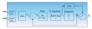
  1. How speed can be calculated from the analog output of a Resolver?
  2. Does TMDSCNCD28335 has the feature of implementing resolver to digital conversion? If not, then could you suggest other high clock frequency DSP suitable for RDC.
  3. Is there any dedicated ICs available to incorporate RDC for high speed (around 1Lakh RPM) calculation. If yes, then could u suggest the suitable part number for the attached resolver. Also, please guide me regarding interfacing the RDC ICs and the DSP?
  4. Do any model of DSP have independent capability of interfacing with resolvers without use of an RDC kit? TMS320F28379d is developed for motor control applications and has the capability to interface with a resolver. So can i use TMS320F28379d for the attached high speed resolver?
  • Look at this TI paper for more info 

    https://www.ti.com/lit/wp/spry212a/spry212a.pdf

    There is a demo kit available from TI

    https://www.ti.com/tool/TMDSRSLVR

    If you download and install controlSuite from TI, you can find examples at 

    C:\ti\controlSUITE\development_kits\TMDSRSLVR_v1.0\Resolver_f28335

    Hope it helps.

  • Dear Ramesh Ramamoorthy,

    I thank you for your help and support.

    Brief Outline:

    We are working on the control of high-speed machines for speeds up to 1 lac rpm which means a fundamental frequency of  around 1.7 kHz, and a carrier frequency of 40 kHz (for sinusoidal PWM). So, I request you to kindly help me out with the following doubts

    Doubt:

    1) We want to know how much time does it take for the speed sensing and calculation of 1 sample point. As our carrier is of 40 kHz (25 micro sec), so we have to finish the speed sensing by the resolver as well as the involved calculations within 5 micro seconds. Kindly help us understand if this is possible with what we are using currently - TMDSCNCD28335.

    2) If no, then advice us on other alternatives which can be considered.

    Thank you.

  • The method we use has two FIR filters, and it requires nearly 300 cycles max with x335. At 150MHz, it means 2 micro seconds. If you use any other method such as oversampling the sine and cosine, it can be reduced further. We dont have trade off results, but just a pointer for you.

  • Dear Sir,

    May i know the complete time taken to execute one cycle of the control loop (starting from sinq and cosq input to the 'q' output) shown in figure attached from TI paper.

  • Our implementation has FIR filter, that accumulates data over one carrier cycle while updating the sine wave. The 300 cycle mark is during decimation when we extract one data out of FIR filter. During oher instances of ISR, it updates the carrier sine wave and collects ADC data and does an accumulate. When one full cycle is completed, it will do decimation followed by calculation. Our method also uses atan(), if you sine cos cross multiplication approach, you can save some more cycles on x335.

  • May I get the algorithm flow chart along with the carrier frequency and sampling time of ADC?

  • Flowchart is not available per se, the implementation block diagram as you see is all we have in public domain. To generate 10KHz carrier, we generate a 160KHz interrupt where the sine wave generation is addressed by an LUT of 16 entries, and MAC of FIR filter is also implemented in here.  ADC sampling time is less than 1us.