This thread has been locked.

If you have a related question, please click the "Ask a related question" button in the top right corner. The newly created question will be automatically linked to this question.

TMS320F28069F: Motorware V16 speed control issue

Part Number: TMS320F28069F
Other Parts Discussed in Thread: DRV8301, MOTORWARE

I inherited a TI Instaspin motorware based project that runs on a custom board using a DRV8301.  It turns a 24V BLDC motor that is embedded in a water pump. The software was based on motorware v16 proj_lab11a, so much so my predecessor didn't even bother to create a new instance and just edited the original V16 project.  The issue with the controller is that at a speed just below nominal rated RPM of 3450 the motor spins up out of control.

The test setup is the water pump/motor in water with a flow meter and I'm using a multimeter to measure the RMS voltage across two of the motor leads.  I can control the pump speed with a pot on the custom board and monitor the controller via the emulation probe and debugger.  With 36V supplied to the board I can control the motor up to about 3200 rpm as reported by the debugger.  This puts about 24.5V RMS across the two phases of the motor.  Any higher and the motor takes off at high speed.  I can tell the motor is spinning fast as the flow rate jumps way up, and the voltage across the two phases jumps to 27.5V RMS.  The interesting part is the controller thinks the motor is running at the commanded RPM of about 3300.  Also interesting is if I increase the supply voltage the controller is able to stay in controller at a faster speed.  Still spins out of controller at some point, but better.  Also, note I'm able to control the pump/motor smoothly through it's whole range with controller board from another manufacturer.

It looks like my predecessor was in the process debugging the issue as he has commented out the speed PI controller calls.  Not sure what that was to accomplish.  I started moving the project over to V18 in hopes something in there would fix the issue, but I've since gotten feedback that it probably wouldn't.

Any suggestions or thoughts would be appreciated.

Thanks, John

  • As replied to a thread you posted. The lab11a was not changed in MW18 compare to MW16. You might tune the speed controller, and help to capture some motor phase current waveforms that could help us to understand your questions. Meanwhile, please monitor the output of the speed controller, and the vector voltage (gMotorVars.Vs) to check if the maximum current or the bus voltage is enough for running the motor at high speed with load.

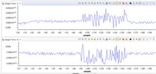
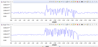
  • Here are waveforms of Vd, Vq, and Vs during the out of control condition.  Vs maxs out at about 0.5.

    Interesting to note that during this out of control condition Speed_krpm is not to far off from SpeedRef_krpm.  That is the controller thinks it has control of the motor but I can tell from the flow meter and voltage going to the motor that it does not.

    (5) = Vd, (6) = Vq

    (5) = Vd, (7) = Vs

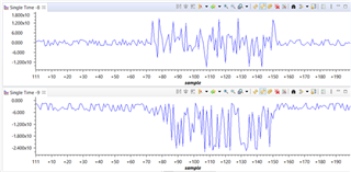
  • (8) = Id_A, (9) = Iq_A

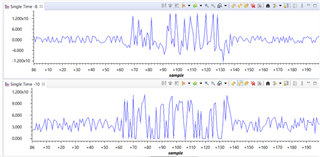
    (8) = Id_A, (10) = Is_A

  • I decided to investigate the effects of changing the PWM Freq on the control issue.  I raised USER_PWM_FREQ_kHz from 10 to 12.  However, this caused the out of control issue to happen at a lower rpm.  So I starting decreasing the PWM Freq and it improved control at higher rpm.  With USER_PWM_FREQ_kHz set at 5.0 I'm able to control the motor at the required higher rpm.

    The question I have is, is this the correct way to solve this issue or should I be adjust something else?

    Thanks, John

  • The maximum switching frequency depends on the power inverter on the hardware board, and is also limited to the execution time of the ISR code.

    You should select the right PWM frequency according to these two mentioned above and the control response you want.