This thread has been locked.

If you have a related question, please click the "Ask a related question" button in the top right corner. The newly created question will be automatically linked to this question.

LAUNCHXL-F28027F: Motor drive current is distorted at high RPM

Part Number: LAUNCHXL-F28027F

Hello Expert,

Currently, with the combination of "LAUNCH XL-F28027F" + "BOOST XL-DRV8301" . Our customer is driving a motor, but in the high rpm range (20000 to 30000 [RPM]) with the load applied, The sinusoidal waveform of the current is distorted and has a whiskered shape.

The brushless permanent magnet motor is rotated by the sensorless vector control of InstaSPIN-FOC.
(Motor equipment constants used: Number of counterpoles 3, phase resistance 0.163 [Ω], Φa = 1.61 × 10⁻³ [Wb], Ld, Lq = 0.129 [mH])

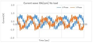
The figure below shows the phase current waveform of the motor when rotating at 30k [rpm]. In the low rpm range, the waveform shape is close to a sine wave, but in the high rpm range such as 30k [rpm], Although it is rotating, the waveform is disturbed as shown in the figure below. At this time, the motor is in a no-load state. 


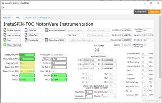
The each gain setting values are as shown in  below.

Regards,

A.Fujinaka

  • That could be normal that the PWM switching and control frequencies is not enough or the motor model is not accuracy at high speed with high current. You might try to implement a higher PWM and control frequencies, and get the inductance vs current curve for motor manufacturer to set the new inductance value on-the-fly to maximize the accuracy of FAST.  

  • Hello Luo,

    Thanks for your reply.   I communicated with my customer.
    Since they could rotate at high speed  with this motor on another drive, they think the motor model is good. So they think your answer seems correct, which is, PWM switching and control frequency are not enough. They know how to change the PWM switching but don't know how to adjust the control frequency. Could you tell it?

    Regrds, Fujinaka

  • You might find the following codes in user.h, the control frequency depends on these parameters marked RED. The maximum supporting control frequency could be 15~20kHz that depends on the execution time of ISR.

    #define USER_PWM_FREQ_kHz                (45.0)

    #define USER_NUM_PWM_TICKS_PER_ISR_TICK        (3)

    #define USER_NUM_ISR_TICKS_PER_CTRL_TICK       (1) 

    #define USER_ISR_FREQ_Hz           ((float_t)USER_PWM_FREQ_kHz * 1000.0 / (float_t)USER_NUM_PWM_TICKS_PER_ISR_TICK)

    #define USER_CTRL_FREQ_Hz          (uint_least32_t)(USER_ISR_FREQ_Hz/USER_NUM_ISR_TICKS_PER_CTRL_TICK)

  • Hello Luo,

    Could yo uplease  explain the meaing of these parameters?

    #define USER_NUM_PWM_TICKS_PER_ISR_TICK       

    #define USER_NUM_ISR_TICKS_PER_CTRL_TICK

    Regards,

    A.Fujinaka

  • Decimation number that defines the number of ticks between module execution. 

    USER_NUM_PWM_TICKS_PER_ISR_TICK, the number of PWM periods per interrupt

    USER_NUM_ISR_TICKS_PER_CTRL_TICK, the number of controller clock ticks per current controller clock tick.

    You might find details in the user.h, or in chapter 4.3 of instaspin user's guide (InstaSPIN-FOC and InstaSPIN-MOTION User's Guide (Rev. H)).