This thread has been locked.

If you have a related question, please click the "Ask a related question" button in the top right corner. The newly created question will be automatically linked to this question.

TMS320F280025C: ADC internal reference shift.

Part Number: TMS320F280025C

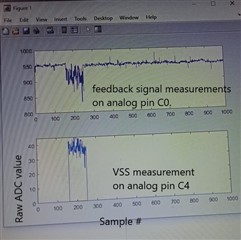
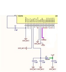
I am facing a strange issue with our power conversion board. The TMS320F280025C is driving some IGBTs and also doing analog measurements for the feedback signal. We are observing step changes in the feedback signals in somewhat periodic pattern while the oscilloscope view does not show any such pattern. While doing troubleshooting we decided to do some readings of the ground voltage i.e.  VSS. There is an interesting observation that Vss measurement is also having step jumps exactly at the some points as the feedback signal. Since VSS, VSSA and VREFLO are all connected together so I am expecting that I should be getting zero voltage reading all the time. I am unable to understand why ADC is reading as large as 250 mV on this pin. The only thing that comes to my mind is that there could be some potential difference between VSS & VREFLO pins at some instants. We have used a 2.2 uF capacitor between VREFHI and VREFLO pins. The following circuit is implemented for ADC reference and power pins:

Please let me know if more details are required and help me in fixing the issue.

  • I am attaching a picture for better explanation of the issue:

  • Hi Asad,

    It may be possible that you have some ground-bounce in your system, but it seems to persist for about 100 ADC samples, which is seemingly quite a long time.  I think you'd also probably be able to see it with a scope based on the magnitude. Is anything else going on in the system at the same time as the erroneous readings? 

    It could also be possible that the ADC is having some core issue which affects all measurements.  It'd be good to double check the VDDA and VREFHI voltages to see if they have some droop or noise during these periods.  It also might be worth checking if any pin on the device is in an under-voltage (below VSS - 0.3V or below VSSA - 0.3V) or over-voltage condition (above VDDIO + 0.3V or above VDDA + 0.3V) during these periods.   

    Finally, what does your software look like?  Are you sure the device is operating with SYSCLK and ADCCLK within expected range (<= 100MHz for SYSCLK and <= 50MHz for ADCCLK)?  What S+H duration are you using for sampling your ADC channels?  Is the sampling ePWM driven with a fixed frequency and phase, or something more complicated?   

  • Dear Devin Cottier,

       Thankyou very much for a very valuable reply. We are checking the supply voltages as mentioned by you. I would like to answer the last paragraph of your reply as below:

    Basically we are doing MPPT on this controller. The analog inputs are measuring PV voltage and currents (fed by PV simulator) and the output is a single PWM output. We have noticed that the ground voltage as measured by the ADC is having a shift right at the instant when PWM duty cycle is updated. The duty cycle is being updated every 100 uSec (10 KHz). The PWM frequency is 20 KHz.

    The ADCs are set to be triggered by the PWM SOCA event  with sampling time of 80 nSec as shown below.

    ADC_setupSOC(ADCA_BASE, ADC_SOC_NUMBER0, ADC_TRIGGER_EPWM4_SOCA,
    ADC_CH_ADCIN6, 8);

    The SOCA is set to be triggered  when time base counter is zero on every second event as  shown below:

    EPWM_setADCTriggerSource(EPWM4_BASE,EPWM_SOC_A,EPWM_SOC_TBCTR_ZERO);
    EPWM_setADCTriggerEventPrescale(EPWM4_BASE,EPWM_SOC_A,2);//Trigger on every second event
    EPWM_enableADCTrigger(EPWM4_BASE,EPWM_SOC_A);

    So sampling is also done @10 Kilo samples/second.

    The system clock is set at 100 MHz with an external 20 MHz Oscillator. The ADC clock should be 50 MHz as set by the below instructions:

    ADC_setPrescaler(ADCA_BASE, ADC_CLK_DIV_2_0);
    ADC_setPrescaler(ADCC_BASE, ADC_CLK_DIV_2_0);

    Please let me know if more information is needed. 

  • Hi Asad,

    I think your clock settings, the ADC settings, and your sampling method seem good. 

    You say that the erroneous ADC readings seem to correspond to a change in ePWM duty cycle?  Does the duty cycle stay the same or similar for all the samples that are erroneous? (since the erroneous condition seems to exist for many consecutive samples). 

    If your setup allows it, you might try to keep the input voltage constant, but sweep the duty cycle systematically.  Still keep the IGBT switching if possible, because what might be happening is that based on a given duty cycle the IGBT switching occurs closer or further away from the ADC sampling instant.  When close to the sampling instant, you might get noise coupling into the ADC via your PCB design or setup.  You can also try turning off the IGBT switching and running a similar experiment to see if the issue resolves. 

    Alternately, you can try sweeping the S+H duration, increasing from 80ns.  Since the critical sampling instant for the ADC is the end of the S+H time, increasing the S+H duration will push back the time when the sample occurs relative to the IGBT switching.  Note: increasing the S+H could also help (possibly in a confounding way) if the impedance of the source driving the ADC is high (and/or if the bandwidth of the driver is low).  See https://www.ti.com/lit/an/spract6/spract6.pdf for more information.     

  • Dear Devin Cottier,

       I have forwarded your troubleshooting guide lines to our testing team. They have a concern that there might be some discontinuity in the PWM when the duty cycle is changed. I would request you to check if my PWM settings and duty cycle update process correct.

    The PWM is configured using the function as shown below:

    //base is the PWM channel to be configured.
    //type can be either independent or complementary
    void initEPWMWithoutDB(uint32_t base, bool type)
    {
        //
        // Set-up TBCLK
        //
        EPWM_setTimeBasePeriod(base, EPWM_TIMER_TBPRD);
        EPWM_setPhaseShift(base, 0U);
        EPWM_setTimeBaseCounter(base, 0U);
        EPWM_setTimeBaseCounterMode(base, EPWM_COUNTER_MODE_UP_DOWN);
        EPWM_disablePhaseShiftLoad(base);
    
        //
        // Set ePWM clock pre-scaler
        //
        EPWM_setClockPrescaler(base,
                               EPWM_CLOCK_DIVIDER_1,
                               EPWM_HSCLOCK_DIVIDER_1);
    
        //
        // Set up shadowing
        //
        EPWM_setCounterCompareShadowLoadMode(base,
                                             EPWM_COUNTER_COMPARE_A,
                                             EPWM_COMP_LOAD_ON_CNTR_ZERO);
    
        //
        // Set-up compare
        //
        EPWM_setCounterCompareValue(base, EPWM_COUNTER_COMPARE_A, EPWM_TIMER_TBPRD/4);
        if (type==complementary)
            EPWM_setCounterCompareValue(base, EPWM_COUNTER_COMPARE_B, 3*EPWM_TIMER_TBPRD/4);
    
        //
        // Set actions
        //
        EPWM_setActionQualifierAction(base,
                                          EPWM_AQ_OUTPUT_A,
                                          EPWM_AQ_OUTPUT_LOW,
                                          EPWM_AQ_OUTPUT_ON_TIMEBASE_ZERO);
        EPWM_setActionQualifierAction(base,
                                          EPWM_AQ_OUTPUT_A,
                                          EPWM_AQ_OUTPUT_HIGH,
                                          EPWM_AQ_OUTPUT_ON_TIMEBASE_UP_CMPA);
        EPWM_setActionQualifierAction(base,
                                          EPWM_AQ_OUTPUT_A,
                                          EPWM_AQ_OUTPUT_NO_CHANGE,
                                          EPWM_AQ_OUTPUT_ON_TIMEBASE_PERIOD);
        EPWM_setActionQualifierAction(base,
                                          EPWM_AQ_OUTPUT_A,
                                          EPWM_AQ_OUTPUT_LOW,
                                          EPWM_AQ_OUTPUT_ON_TIMEBASE_DOWN_CMPA);
    
        if (type==complementary)
        {
            EPWM_setActionQualifierAction(base,
                                              EPWM_AQ_OUTPUT_B,
                                              EPWM_AQ_OUTPUT_LOW,
                                              EPWM_AQ_OUTPUT_ON_TIMEBASE_ZERO);
            EPWM_setActionQualifierAction(base,
                                              EPWM_AQ_OUTPUT_B,
                                              EPWM_AQ_OUTPUT_HIGH,
                                              EPWM_AQ_OUTPUT_ON_TIMEBASE_UP_CMPB);
            EPWM_setActionQualifierAction(base,
                                              EPWM_AQ_OUTPUT_B,
                                              EPWM_AQ_OUTPUT_NO_CHANGE,
                                              EPWM_AQ_OUTPUT_ON_TIMEBASE_PERIOD);
            EPWM_setActionQualifierAction(base,
                                              EPWM_AQ_OUTPUT_B,
                                              EPWM_AQ_OUTPUT_LOW,
                                              EPWM_AQ_OUTPUT_ON_TIMEBASE_DOWN_CMPB);
        }
    
    }

    The duty cycle update is done by calling the following function:

    inline void updateEPWMDuty(uint32_t base,uint16_t duty_count,bool type)
    {
        EPWM_setCounterCompareValue(base, EPWM_COUNTER_COMPARE_A, duty_count);
        if (type==complementary)
                EPWM_setCounterCompareValue(base, EPWM_COUNTER_COMPARE_B, EPWM_TIMER_TBPRD-duty_count);
    
    }

    We will update you if there is a new finding at our side.

  • Hi Asad,

    I'll ask an ePWM expert to take a look at your duty cycle update method. 

  • Your way of updating is okay. BUT remember to this in the EPWM interrupt or at a known place in the EPWM period cycle so the shadowing doesnt happen at the shadow event boundary.

  • In my code the EPWM SOCA (setup to trigger when time base counter is equal to zero) triggers ADC conversions. The SOCA is prescaled by 2 so that ADC conversion is triggered on every second PWM start of cycle.The ADC end of conversion generates an interrupt in which control task is called. The control task takes about 40 uSec to complete. After control task is finished the value of duty cycle is updated in the same interrupt. I have checked on the oscilloscope that the duty cycle transition is smooth although update is delayed by one PWM cycle every time. What happens if shadowing happens at the shadow event boundary?. Will it create any irregularity leading to abnormal switching noise generation?

  • The way you have it implemented should be fine. If you were writing to the duty/period at random times in your application main() then you would have this issue. but your implementation doesnt do that.

  • Dear Nima Eskandari,

        I have a small query regarding the EPWM SOCA event. We do have a lot of switching noise at the PWM transitions. There is one proposal to change the ADC trigger on the run depending on if the duty cycle is less than 45 % or greater than 55% (hysteresis of 10 to avoid frequent change). I have tried implementing this logic but the ADC appears to be triggered always on the same settings as the initialization code. I have implemented the following logic in the control ISR for changing EPWM ADC start of conversion event:

    if (duty_cycle < 45)
       {
        EPWM_setADCTriggerSource(EPWM4_BASE,EPWM_SOC_A,EPWM_SOC_TBCTR_ZERO);
        EPWM_setADCTriggerEventPrescale(EPWM4_BASE,EPWM_SOC_A,2);//Trigger on every second event
        EPWM_enableADCTrigger(EPWM4_BASE,EPWM_SOC_A);
        }
    else if (duty_cycle > 55)
       {
        EPWM_setADCTriggerSource(EPWM4_BASE,EPWM_SOC_A,EPWM_SOC_TBCTR_PERIOD);
        EPWM_setADCTriggerEventPrescale(EPWM4_BASE,EPWM_SOC_A,2);//Trigger on every second event
        EPWM_enableADCTrigger(EPWM4_BASE,EPWM_SOC_A);
        }
    else ;

    Please check if the implemented logic is sufficient or I need more actions to change EPWM SOCA trigger.

  • Actually the trigger point is changing. I was not observing it correctly. However there is one issue that there is one extra ADC conversion when I change the ADC trigger point. Normally ADC conversion is triggered for every second SOC event but when I change the SOC trigger point then there are two conversions in two consecutive PWM cycles. This might be an issue as ADC conversion triggers control ISR. So there will be one extra aperiodic control interrupt. Please refer to the picture below: 

    The red dots show ADC conversions in two consecutive PWM cycles.

  • Yes when you do the CHANGE, in that one cycle you get one at the PRD and one at the ZRO. 

  • Dear Devin Cottier and Nima Eskandari, 

      Thank you very much for your valuable support. We were getting ADC related issues with the TMS320F280025C launch pad. After getting our production PCBs with low pass filters at ADC inputs, we are getting stable readings. We suspect that the power supply from the USB to TMS launchpad or the absence of low pass filters on the launchpad was causing shift in the ADC values. We can close this thread now.