This thread has been locked.

If you have a related question, please click the "Ask a related question" button in the top right corner. The newly created question will be automatically linked to this question.

SM320F28335-EP: New device seems locked

Part Number: SM320F28335-EP
Other Parts Discussed in Thread: TMS320F28335, UNIFLASH, TMDSCNCD28335

Hello,

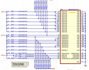
I'm working with a self developed board with the SM320F28335-EP device,

Code Composer Studio : Version: 10.4.0.00006 and

Spectrum Digital XDS100V2 TI-14PIN JTAG Emulator.

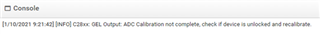
Triyng at first time to debug some easy application (led blink example) I received allways the same error:

C28xx: GEL Output:
ADC Calibration not complete, check if device is unlocked and recalibrate.C28xx: Flash Programmer: Warning: The configured device (TMS320F28335), does not match the detected device (). Flash Programming operations could be affected. Please consider modifying your target configuration file.
C28xx: GEL Output:
ADC Calibration not complete, check if device is unlocked and recalibrate.C28xx: File Loader: Verification failed: Values at address 0x08081@Program do not match Please verify target memory and memory map.
C28xx: GEL: File: C:\Users\103011\workspace_v10\Example_2833xLEDBlink\Debug\Example_2833xLEDBlink.out: a data verification error occurred, file load failed.

After checking some forums and finding threads with similar issues, I fogot to use Code Composer and try to read directly the memory of the device with UniFlash (Version: 6.4.0.3394).

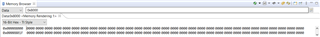
With UniFlash I can read the memory of the device. Because it seems to have a locked device, I have checked the register 0x33fff8 with the next results:

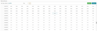
0x0000 in all registers.

I seems that the device is locked.

In the "Setting & Utilities" tab of UniFlash, I have try to unlock the device, then to test the Checksum, to change the password, to perfomr Frequency test and I became allwais the same error:

[28/9/2021 13:43:55] [ERROR] C28xx: Flash Programmer: Error calculating checksum. Device is locked or not connected. Operation cancelled.

[28/9/2021 13:45:17] [ERROR] C28xx: Flash Programmer: Error unlocking flash memory. Device is still locked

[28/9/2021 13:45:37] [ERROR] C28xx: Flash Programmer: Error unlocking flash memory. Device is still locked

With a new (Completely untouched!!) board, I have removed all interface between device and watchdog, external memories or other devices. I have tried only (using UniFlash) to read the memory, then to check the 0x33fff8 address (password locations) and to unlock the board and the results are exactly the same as before.

In my design, the JTAG interface is performed as in the Docking STN (R-3) board. I think all is correct.

Pin XRS# (pin 80) is not connected. Pins (XA12, XA13, XA14 and XA15) are at high level (3V3).

Pin VDD3VFL is powered at 3V3.

It is necesary to perform any special procedure to work with a completey new device before first programming?

Can somebody help me?

All inputs are welcome.

Thank you and best regards

Iñigo

  • Inigo,

    Thanks for reaching out to the E2E forum.  I'd like to put the device in "Check Boot Mode" this will stay in a loop inside the BROM and not attempt to execute any code.

    For this boot mode the pin config is as follows XA15 = low, XA14 = low, XA13 = high, XA12 = high.

    Once you power up with this config, let's try to just connect vs loading a program.

    To do this, right click on your .ccxml target file and "launch selected configuration"  This should bring up the debug aspect of CCS.  Once there, right click on the C28x CPU and "connect".

    From the top ribbon of CCS you should see a "Scripts" button, click this and go to Code Security Module, and Unlock CSM.  This will execute a dummy read of the passwords that is required to unlock the device(even if there is no password programmed i.e. 0xFFFF). 

    Once you do this, open a memory window into 0x8000 and see if you still observe all 0x0000, or just random data.  We can proceed from there based on your reply.

    Best,

    Matthew

  • Hi Matthew,

    thank you very much for your very quick answer.

    I have try your proposal and following you can see the 0x8000 memory registers:

    all registers content 0x0000.

    looking forward for your answer.

    Thank you again

    Iñigo

  • Inigo,

    Thanks for trying this, it does appear that there is a non-erased value in the CSM locations of the flash.  All devices ship from TI in the erased state(0xFFFF in all address in the flash); so this should not be the case.

    I would check the voltage levels of all the supply pins that they are correct.  In this case I would pay special attention to the pin VDD3VFL, which is the power supply pin to the flash.  It should be at the same potential as the other VDDIO pins, i.e. 3.3V nominal.  Sometimes, because this pin has a unique name, customers have not tied it to the 3.3V rail.  Lack of power on this pin would cause abnormal behavior in the flash.

    Best,

    Matthew

  • Hello Matthew,

    thank you very much for your help.

    We have double check the power supply in mentioned pins and it is 3.25V stable voltage. Attached you can find the schematic we have implemented. The only particularity is the LC circuit that we always implement for filtering purpouses.

    The device is completely new, never used in other projects.

    Please, do not hesitate to propose us any other tests to perform. We are completely blocked.

    Thank you very much again and best regards.

    Iñigo

  • Inigo,

    Thanks for sharing the power portion of the schematic.

    Let's try the following: replace the 100nF cap on VDD3VFL with a 1uF or larger(I'm assuming the caps is reasonably close to the device and see if there is any difference in behavior.  I'm trying to see if there is some transient response for current to the flash array that is causing the issue.

    Another thing to try independent of the above, I want to try 2 different passwords combinations to ensure that the device did leave TI in erased(0xFFFF) state.

    For one time please use the below password to the DCSM(I think you can just modify the GEL file from the default of all 0xFFFF).

    1) 0x0000, 0xFFFF, 0x0000, 0xFFFF, 0x0000, 0xFFFF, 0x0000, 0xFFFF

    2) 0xFFFF, 0x0000, 0xFFFF, 0x0000, 0xFFFF, 0x0000, 0xFFFF, 0x0000

    The above are test patterns that should be erased before the device ships from TI, but its worth a try to see if this is the issue, the only other option is to initiate a return procedure(RMA) based on the device being locked and get replacement devices.

    Best,
    Matthew

  • Hello Matthew,

    thank you for your help.

    We have try to replace the actual 100nF capacitor by a 1uF one. All capacitors are close to the DSP pins. The result is the same the DPS seems to be locked.

    The second idea, trying two diferent passwords also doesnt work.

    Maybe we need to perform the "Return Procedure (RMA)"  you mentioned in previous email.

    How can I proceed?

    Thnak you again!!

    Iñigo

  • Inigo,

    This page details the process to follow depending on where the device was purchased(distributor or TI).

    https://www.ti.com/support-quality/additional-information/customer-returns.html?keyMatch=CUSTOMER%20RETURNS

    Best,
    Matthew

  • Good morning Matthew,

    thank you for your email.

    We have spoken with our PCB manufacturer to change the actual DSPs with new ones. Also our manufacturer is surprised with this situation that had not occurred before. At this stage we have assembled four identical PCBs and all have reported the same problem with de DSP.

    Before to change the DSP we want to assure that the new ones come from another batch. Therefore new purchase will be performed directly to TI.

    Thank you very much for your help and best regards.

    Iñigo

  • Inigo,

    Thanks for the update, let me know if I can be of more assistance.

    Best,

    Matthew

  • Hello again Matthew,

    we are very surprised with what happened with the four completely new (and buyed to an official TI distributor) TMS320F28335 units.

    If we assume that the hardware design is correct and we have not done anything wrong, it seems that the TMS320F28335 were defective.

    Is this a unique case? Has it happened in other occasions?

    Could it be due to an improper use of our side?

    Dou you recomend any specific procedure for the first test when the new boards arrive?

    Thank you and best regards

    Iñigo

  • Inigo,

    I am surprised as well, esp over all 4 units as you have mentioned.  All devices are shipped in erase state from TI, and I believe an erase check is the final or one of the final tests before we ship the devices.  Going through the RMA procedure the devices will come back to TI for re-test where we can confirm that the CSM is not erased, re-test, and look at the lot history to understand if there is some underlying issue or not.

    To your question, this is unique from my perspective as well as given the maturity of this device that this could happen.

    In terms of improper use, accidentally locking the CSM is possible if the flashing process is interrupted before it completes.  This could be a power event, an un-intended reset (XRSn) during programmation, or if the JTAG(assuming that was the programming method) was disconnected during the flash event.  If you were using JTAG with either CCS or other programmer IDE, any fault of this nature would result in an error getting displayed at the time, however.

    In terms of an initial checkout, I would advise simply connecting with Code Composer and/or Uniflash and "unlocking" the device by reading the password locations.  Since there was no program attempt, this should be 100% erased from TI and always pass.

    Do you happen to have a TMDSCNCD28335 controlCARD?  Just to use to connect to CCS/Uniflash to confirm the unlocking process on a reference device?  It might also be beneficial to do a quick schematic comparison between your design and the control CARD just to verify the keep alives/power planes are the same.

    Best,

    Matthew