This thread has been locked.

If you have a related question, please click the "Ask a related question" button in the top right corner. The newly created question will be automatically linked to this question.

TMS320F28334: Problem with GPIO22 and GPIO52 as inputs

Part Number: TMS320F28334

I am using GPIO20 thru GPIO24 and GPIO50 thru GPIO58 as inputs.  They are all configured as inputs,and all work properly with the exception of GPIO22 & GPIO52.  Is there something different about thes two GPIUO points?

  • There are no differences that I know of.

    Start by checking the configuration during runtime. Verify GPADIR and GPBDIR. Verify GPAMUX2 and GPBMUX2. This should verify they are inputs and are being used as GPIO, not for some peripheral function.

    Secondly, how are you toggling the GPIOs? Back to back writes to certain registers can get lost.https://processors.wiki.ti.com/index.php/General_Purpose_IO_(GPIO)_FAQ_for_C2000#Q:_Back-to-back_DAT_register_writes_do_not_work_as_expected 

    The whole article above is probably worth a read.

    Regards,
    Cody 

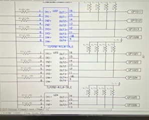
  • Thanks for the response Cody.  I have checked the MUX and DIR registers with GEL and they are OK.  I also put in an infinite loop right after power up to ensure that nothing else would access those registers.  The GPIO pins are connected to the outside world through an optical isolator, TLP292-4(LA-TR,E.  There is a 4.7k pullup connected to 3.3 volts on the GPIO pin  The other 46 pins I am using for inputs are connected the same way and work properly.

    The article you referenced has been removed. 

  • The article you referenced has been removed. 

    I think the processors Wiki is now only visible internally to the TI network.

    Think the article is now in [FAQ] C2000 GPIO FAQ

    Failing that, found an archived copy of the original processors Wiki page at https://web.archive.org/web/20200930225801/https://processors.wiki.ti.com/index.php/General_Purpose_IO_(GPIO)_FAQ_for_C2000 

  • Thank you for the link Chester.  I am looking at the GPIO pin with a scope.  When I try to switch the input (through the optoisolator) , the pin does not change state.  All of the other inputs work properly.   I can set a breakpoint to trap when the input goes on, and can trigger it by grounding the GPIO pin directly.  I don't know if the 4.7k  pullup resistor is of too low a resistance to allow the isolator to ground the GPIO pin.

  • I don't know if the 4.7k  pullup resistor is of too low a resistance to allow the isolator to ground the GPIO pin.

    Can you measure the voltage on the GPIO22 & GPIO52 pins when the associated optical isolator is ON, to see how close the input is to VIL ?

  • the voltage on the GPIO pin is 3.1 volts.  It does not change when the optoisolator is on.  The optoisolator input does change from 24 volts to 0 volts.

  • It does not change when the optoisolator is on. 

    Have you got more than one board which shows the issue?

    Wondering if a fault on the optoisolator channels connected to the GPIO22 & GPIO52 pins, rather than in the GPIOs in the TMS320F28334.

  • I have tested 5 boards, and all exhibit the same behavior.

  • Fred,

    it does seem that must be cashed on an internal server. But as Chester pointed out the information can be found in that FAQ. Is it safe to assume that you are not using back-to-back writes to the DAT register? 

    The device should be able to over power a 4.7k pull-up resistor, but it might be worth depopulating that resistor to verify it isn't the issue. From this perspective I'm more expecting an assembly issue, or since this is on 5 boards, maybe the wrong value is listed in the BOM? Its an easy problem to rule out though, so why not.

    I am unsure how you used the GEL to verify the register values. I would recommend reading them back using the Registers viewer assuming that you can run while connected to CCS. You can access this register by going to "View-> Registers". Be sure to click on the continuous refresh button.

    Regards,
    Cody 

  • Hi Cody  Yes, thank you, I did find the doc you were referring to.   As these GPIO pins are used as inputs, I am not writing anything to the DAT registers.    

    I checked the value of all the resistors are they are correct, but that was a good suggestion.   i did change the two resistors to 16k to see if a weaker pullup would work. That did not work.  Removing the pullup on GPIOon the pin had no effect either.

    This is the circuit I am using.  All 48 GPIO pins that I am using as inputs are all connected the same way, but only 2 of them don't operate properly.  I have checked all of the MUX, PUD and DIR registers by setting a watch after the code was running.  All registers are correct.

    I can relocate my field inputs to different GPIO pins, (but would rather not).  Thanks for any additional help you can provide.

  • Fred,

    Sorry for the confusion, I see you indicated you were using the GPIO as an input earlier in the thread.

    Just to confirm. when you drive 3.3V on the GPIOs you see a 1, and when you force the node to 0V you can see a 0 in the C2000 device? This would indicate to me that the device is setup and working correctly. There is a Very weak pull up inside the device that can be enabled or disabled, but this is NOT strong enough to affect your optocoupler. 

    If swapping to a new optocoupler doesn't fix the issue perhaps you could de-solder an adjacent pin and cross the Optocopuler channels. This can likely be easily done with GPIOs 21 and 22. If the problem follows the optocoupler channel we can rule out any C2000 issues. 

    Regards,
    Cody  

  • I Cody. I just read your answer and had the same idea. I tried swapping the channels on the isolator and found that the processor was working correctly.  I then rechecked my board layout very closely and found that the traces from pin 13 on the isolators to ground were missing for those two points.  The misstraces are very short, which is why I missed them. I added a solder bridge to ground the pin and all is working properly!  
    many thanks for your help with this!!

  • Fantastic to hear that you found the issue. Sorry to hear about the upcoming hardware revision.

    Best of luck,
    Cody