This thread has been locked.

If you have a related question, please click the "Ask a related question" button in the top right corner. The newly created question will be automatically linked to this question.

TMS320F28384D: JTAG probe not connecting PCB prototype F28384dptps

Part Number: TMS320F28384D

Greetings Forum, 

I'm a bit stuck debugging issue im having hence the post.
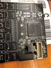
I created new PCB with a micro after studying  abit the reference design files for a F28388D microcontroller from TI folder. I was not able to obtain this micro due to chip shortages.

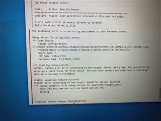
After soldering the pcb components power, supplies decoupling caps, inductors I was expecting to have some communication with the microcontroller. Im getting error
IcePick_C_0: Error connecting to the target: (Error -183 @ 0x0) The controller has detected a cable break far-from itself. The user must connect the cable/pod to the target. (Emulation package 9.3.0.00032)

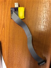
Im using a FT2232HL cheap adapter from ebay as a programmer.I  can use used it with  another micro (F28069M) custom PCB that I designed. 
Im using a .F28388D.ccxml for a target configuration.

I checked the pins for bridges and shortages and pins correct voltages on the 3.3V and 1.2V rails.
I also tried suppling the power from the probe with no luck.

What should I check for next.

Im attaching pdf of the schematic for eagle.mcupdf.pdf

  • I don’t have access to the board at the moment but will try the pin 177 connected to ground. But oddly remember reading that the power pad technical document stating it can be left floating. Data sheet is a bit weird it says pin 177,178,179… connected to ground but chip has 177 pins. Will know more monday.

  • Hi Jakub,

    Please also go through the comprehensive JTAG guide we have here and let us know if you are still having issues.

  • Hi Frank I'm still having issues.
    I believe i have soldered the epad underneath the chip.
    Would the eeprom settings be different for a F28069 processor on the xds100 probe?

  • Hi Jakub,

    A few questions:

    1. Are you still getting the same error or is the error different now?

    2. What changes did you make to the design after going through the JTAG connection guide?

    3. It's not very clear to me. You are or aren't using XDS100 with the TMS320F28384D device?

    4. Do you have any bulk caps on the supply pins i.e in uF range? I only see 100nF caps.

    5. Are you able to measure the current for the 3.3v and 1.2v rails while the device is powered?

  • Thanks for getting back.
    1. Yes its the same error. Its the same error as when probe is on its own without connecting to pcb.

    2. I ordered new pcb with big epad pin connected to ground this time

    3. Iam using it, but I have the same probe working with another micro I used in the past. This is for fault finding. If the probe is working with different micro maybe can help pinpoint where the problem is located.

    4. No caps in that range. The only ones that are there are on schematic.

    5. I will try to do that and comeback to you

    6. Some pics of the stuff 

  • 5. Have found problem here

    9.6mA 1.2V rail
    3.3V close to 0mA

    But when measured with mustimeter the pins appear to have 3.3V supplied.  

  • Jakub,

    Rather than going back and forth with different items for you to try, please go through the flow chart in this guide -> https://www.ti.com/lit/an/spracf0/spracf0.pdf. The flowchart is on pg 5. If the issue is not solved after that, let us know and we can take a deeper look.

  • I resolved the issue by finding out I have not had couple important connections on the debugger.
    There was a loopback connection missing as well as pull down and pullup resistor on some pins for that are on the debugger and not part of the idc cable lead.

    It was pin 28,32,40,41 on the ft2232h

    This was the main issue.

    Second issue.
    After I worked it out i discovered I have chosen wrong power supply for 1.2V rail. Confused 3.3V as the one that meant to be bigger sized one for current powering the core. Its not the case because 1.2V is the core.
    Hope this helps anyone Slight smile

    Is there any good resource for explanations what the 28,32,40,41 or other pins are for? The debugger xds connections and pullups seems to vary between different micros. Is the eeprom setting always the same for different micro families? Is the ft2232 the only option? It seems to be very scarce in stock. Do there exist instruction to build a probe around different ic?

  • Hi Jakub,

    Glad to hear the issue is resolved! Let us know if you run into more issues.