Other Parts Discussed in Thread: C2000WARE, TMDSCNCD28379D
I have set up SPI between two f28379 launchpads before and I looking to move to a 28379 control card. I was wondering how I might set up SPI on the TMDXIDDK379 developer kit. I want to use SPI between two boards. I read in another post about using J9 external board to board connector and I have the following questions
1. Is using the j9 board to board my only option?
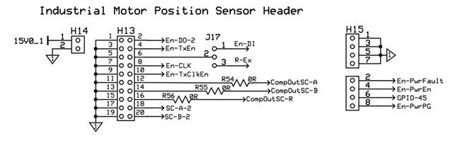
2. Is there a way to set up and use other sections of development board such as h15 or h13 for general GPIOs for easy prototyping? If so how?
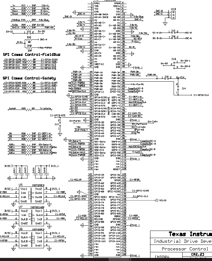
3. Are there places I could solder pins to bring out the SPI signals?
Thank you for your time!