This thread has been locked.

If you have a related question, please click the "Ask a related question" button in the top right corner. The newly created question will be automatically linked to this question.

TMS320F280025C: Trigger CAN with interrupt

Part Number: TMS320F280025C

Hi expert,

I try to set up a CAN communication on my digital loop regulation. I use a peak probe to transmit and see frames on my PC (with PCAN-View). I want to generate CAN interrupts when frames was detected on RX but it doesn't work very well. When I load program I observe frames for a few cycles and after nothing at all why ? 

Can you explain me where is my mistakes please ? You can see my code.

It's difficult to debug because when I compile with optimizations level 2 on RAM it compile but on debug mode I never pass on interrupt, why ? (some calls are not possible ?)  And when I try to compile with no optimization it doesn't compile I have this message : 

error #10099-D: program will not fit into available memory, or the section contains a call site that requires a trampoline that can't be generated for this section. placement with alignment/blocking fails for section ".text" size 0x214cpage 0. Available memory ranges:
RAMLS4567 size: 0x2000 unused: 0x2000 max hole: 0x2000
RAMGS0 size: 0x7f8 unused: 0x7f8 max hole: 0x7f8

I need your help please ! 

Thanks 

Damien

void main(void)
{
    // Initialize device clock and peripherals
    Device_init();

    // Disable pin locks and enable internal pullups.
    Device_initGPIO();

    // Initialize PIE and clear PIE registers. Disables CPU interrupts.
    Interrupt_initModule();

    // Initialize the PIE vector table with pointers to the shell Interrupt Service Routines (ISR).
    Interrupt_initVectorTable();

    can_init();

    // Initialization timer
    timer_cpu_init();
    // Interrupt all of (us) 10ms
    timer_cpu_config(CPUTIMER0_BASE, DEVICE_SYSCLK_FREQ, 10000);

    // Disable sync and clock to PWM
    SysCtl_disablePeripheral(SYSCTL_PERIPH_CLK_TBCLKSYNC);

    Interrupt_register(INT_TIMER0, &isr_timer);
    Interrupt_register(INT_CANA0, &isr_can);


    CPUTimer_enableInterrupt(CPUTIMER0_BASE);
    Interrupt_enable(INT_TIMER0);
    CAN_enableInterrupt(CANA_BASE, CAN_INT_STATUS | CAN_INT_IE0 | CAN_INT_ERROR);
    Interrupt_enable(INT_CANA0);
    CAN_enableGlobalInterrupt(CANA_BASE, CAN_GLOBAL_INT_CANINT0);

    // Enable sync and clock to PWM
    SysCtl_enablePeripheral(SYSCTL_PERIPH_CLK_TBCLKSYNC);

    // Start CAN module operations
    CAN_startModule(CANA_BASE);

    // Start timer for interrupt CAN (to send frames)
    CPUTimer_startTimer(CPUTIMER0_BASE);

    // Enable Global Interrupt (INTM) and realtime interrupt (DBGM)
    EINT;
    ERTM;

    while(1)
    {
        
    }
}
#include "device.h"
#include "can_module.h"
#include "epwm_module.h"

uint16_t rx_tx_parameters[SIZE];

void can_init(void)
{
    EALLOW;
    GPIO_setPinConfig(GPIO_33_CANA_RX);
    GPIO_setPinConfig(GPIO_32_CANA_TX);

    // To visualize timings
    GPIO_setPinConfig(GPIO_40_GPIO40);
    GPIO_setDirectionMode(40, GPIO_DIR_MODE_OUT);
    GPIO_setPadConfig(40, GPIO_PIN_TYPE_STD);
    EDIS;

    CAN_initModule(CANA_BASE);

    CAN_setBitRate(CANA_BASE, DEVICE_SYSCLK_FREQ, 250000, 20);

    CAN_setupMessageObject(CANA_BASE, 1, 0x100, CAN_MSG_FRAME_STD, CAN_MSG_OBJ_TYPE_TX, 0, 0,8);
    CAN_setupMessageObject(CANA_BASE, 2, 0x010, CAN_MSG_FRAME_STD, CAN_MSG_OBJ_TYPE_RX, 0, CAN_MSG_OBJ_RX_INT_ENABLE,8);
}

void timer_cpu_init()
{
    // Initialize timer period to maximum
    CPUTimer_setPeriod(CPUTIMER0_BASE, 0xFFFFFFFF);

    // Initialize pre-scale counter to divide by 1 (SYSCLKOUT)
    CPUTimer_setPreScaler(CPUTIMER0_BASE, 0);

    // Make sure timer is stopped
    CPUTimer_stopTimer(CPUTIMER0_BASE);

    // Reload all counter register with period value
    CPUTimer_reloadTimerCounter(CPUTIMER0_BASE);
}

void timer_cpu_config(uint32_t cpuTimer, float freq, float period)
{
    uint32_t temp;

    // Initialize timer period:
    temp = (uint32_t)(freq / 1000000 * period);
    CPUTimer_setPeriod(cpuTimer, temp);

    // Set pre-scale counter to divide by 1 (SYSCLKOUT):
    CPUTimer_setPreScaler(cpuTimer, 0);

    // Initializes timer control register. The timer is stopped, reloaded, free run disabled, and interrupt enabled. Additionally, the free and soft bits are set
    CPUTimer_stopTimer(cpuTimer);
    CPUTimer_reloadTimerCounter(cpuTimer);
    CPUTimer_setEmulationMode(cpuTimer, CPUTIMER_EMULATIONMODE_STOPAFTERNEXTDECREMENT);
    CPUTimer_enableInterrupt(cpuTimer);
}

__interrupt void isr_timer(void) // generate all of 10ms
{
    GPIO_writePin(40, 1); // for debug

    can_send_frames();

    Interrupt_clearACKGroup(INTERRUPT_ACK_GROUP1);

    GPIO_writePin(40, 0);
}

void can_send_frames(void)
{
    rx_tx_parameters[0] = epwm_dutycyle;

    // Send CAN message data from message object 1
    CAN_sendMessage(CANA_BASE, 1, 8, (uint16_t*) rx_tx_parameters);
}

__interrupt void isr_can(void)
{
    GPIO_writePin(27, 1); // for debug

    CAN_readMessage(CANA_BASE, 2, (uint16_t*) rx_tx_parameters);

    epwm_dutycyle = rx_tx_parameters[0];

    epwm_get_cmpa_from_dutycyle(EPWM1_BASE, epwm_dutycyle);
    epwm_get_cmpa_from_dutycyle(EPWM2_BASE, epwm_dutycyle);
    epwm_get_cmpa_from_dutycyle(EPWM3_BASE, epwm_dutycyle);

    CAN_clearInterruptStatus(CANA_BASE, 2);
    CAN_clearGlobalInterruptStatus(CANA_BASE, CAN_GLOBAL_INT_CANINT0);
    Interrupt_clearACKGroup(INTERRUPT_ACK_GROUP9);

    GPIO_writePin(27, 0);
}

  • I've see can_ex2_loopback_interrupts sample but no sucess

  • Is it to set filtering  ? Do you have an example where filtering is set please ?

    Waiting for your return !

    Thanks

    Damien

  • Hi Damien,

    In the can_ex2_loopback_interrupt example code, there is a function call to start the CAN operations (line #213 CAN_startModule).  This clears Init and CCE bits in the CAN_CTL register to start CAN transactions after initializing CAN, defining RX/TX channels, defining objects, mapping interrupts...etc.  I do not see this function call in your code.  You need to include this function call in your code.

    Regards,

    Joseph

  • Hi Joseph,

    I make the call of this function in my main file line 39.

    void main(void)
    {
        // Initialize device clock and peripherals
        Device_init();
    
        // Disable pin locks and enable internal pullups.
        Device_initGPIO();
    
        // Initialize PIE and clear PIE registers. Disables CPU interrupts.
        Interrupt_initModule();
    
        // Initialize the PIE vector table with pointers to the shell Interrupt Service Routines (ISR).
        Interrupt_initVectorTable();
    
        can_init();
    
        // Initialization timer
        timer_cpu_init();
        // Interrupt all of (us) 10ms
        timer_cpu_config(CPUTIMER0_BASE, DEVICE_SYSCLK_FREQ, 10000);
    
        // Disable sync and clock to PWM
        SysCtl_disablePeripheral(SYSCTL_PERIPH_CLK_TBCLKSYNC);
    
        Interrupt_register(INT_TIMER0, &isr_timer);
        Interrupt_register(INT_CANA0, &isr_can);
    
    
        CPUTimer_enableInterrupt(CPUTIMER0_BASE);
        Interrupt_enable(INT_TIMER0);
        CAN_enableInterrupt(CANA_BASE, CAN_INT_STATUS | CAN_INT_IE0 | CAN_INT_ERROR);
        Interrupt_enable(INT_CANA0);
        CAN_enableGlobalInterrupt(CANA_BASE, CAN_GLOBAL_INT_CANINT0);
    
        // Enable sync and clock to PWM
        SysCtl_enablePeripheral(SYSCTL_PERIPH_CLK_TBCLKSYNC);
    
        // Start CAN module operations
        CAN_startModule(CANA_BASE);
    
        // Start timer for interrupt CAN (to send frames)
        CPUTimer_startTimer(CPUTIMER0_BASE);
    
        // Enable Global Interrupt (INTM) and realtime interrupt (DBGM)
        EINT;
        ERTM;
    
        while(1)
        {
            
        }
    }

    #include "device.h"
    #include "can_module.h"
    #include "epwm_module.h"
    
    uint16_t rx_tx_parameters[SIZE];
    
    void can_init(void)
    {
        EALLOW;
        GPIO_setPinConfig(GPIO_33_CANA_RX);
        GPIO_setPinConfig(GPIO_32_CANA_TX);
    
        // To visualize timings
        GPIO_setPinConfig(GPIO_40_GPIO40);
        GPIO_setDirectionMode(40, GPIO_DIR_MODE_OUT);
        GPIO_setPadConfig(40, GPIO_PIN_TYPE_STD);
        EDIS;
    
        CAN_initModule(CANA_BASE);
    
        CAN_setBitRate(CANA_BASE, DEVICE_SYSCLK_FREQ, 250000, 20);
    
        CAN_setupMessageObject(CANA_BASE, 1, 0x100, CAN_MSG_FRAME_STD, CAN_MSG_OBJ_TYPE_TX, 0, 0,8);
        CAN_setupMessageObject(CANA_BASE, 2, 0x010, CAN_MSG_FRAME_STD, CAN_MSG_OBJ_TYPE_RX, 0, CAN_MSG_OBJ_RX_INT_ENABLE,8);
    }
    
    void timer_cpu_init()
    {
        // Initialize timer period to maximum
        CPUTimer_setPeriod(CPUTIMER0_BASE, 0xFFFFFFFF);
    
        // Initialize pre-scale counter to divide by 1 (SYSCLKOUT)
        CPUTimer_setPreScaler(CPUTIMER0_BASE, 0);
    
        // Make sure timer is stopped
        CPUTimer_stopTimer(CPUTIMER0_BASE);
    
        // Reload all counter register with period value
        CPUTimer_reloadTimerCounter(CPUTIMER0_BASE);
    }
    
    void timer_cpu_config(uint32_t cpuTimer, float freq, float period)
    {
        uint32_t temp;
    
        // Initialize timer period:
        temp = (uint32_t)(freq / 1000000 * period);
        CPUTimer_setPeriod(cpuTimer, temp);
    
        // Set pre-scale counter to divide by 1 (SYSCLKOUT):
        CPUTimer_setPreScaler(cpuTimer, 0);
    
        // Initializes timer control register. The timer is stopped, reloaded, free run disabled, and interrupt enabled. Additionally, the free and soft bits are set
        CPUTimer_stopTimer(cpuTimer);
        CPUTimer_reloadTimerCounter(cpuTimer);
        CPUTimer_setEmulationMode(cpuTimer, CPUTIMER_EMULATIONMODE_STOPAFTERNEXTDECREMENT);
        CPUTimer_enableInterrupt(cpuTimer);
    }
    
    __interrupt void isr_timer(void) // generate all of 10ms
    {
        GPIO_writePin(40, 1); // for debug
    
        can_send_frames();
    
        Interrupt_clearACKGroup(INTERRUPT_ACK_GROUP1);
    
        GPIO_writePin(40, 0);
    }
    
    void can_send_frames(void)
    {
        rx_tx_parameters[0] = epwm_dutycyle;
    
        // Send CAN message data from message object 1
        CAN_sendMessage(CANA_BASE, 1, 8, (uint16_t*) rx_tx_parameters);
    }
    
    __interrupt void isr_can(void)
    {
        GPIO_writePin(27, 1); // for debug
    
        CAN_readMessage(CANA_BASE, 2, (uint16_t*) rx_tx_parameters);
    
        epwm_dutycyle = rx_tx_parameters[0];
    
        epwm_get_cmpa_from_dutycyle(EPWM1_BASE, epwm_dutycyle);
        epwm_get_cmpa_from_dutycyle(EPWM2_BASE, epwm_dutycyle);
        epwm_get_cmpa_from_dutycyle(EPWM3_BASE, epwm_dutycyle);
    
        CAN_clearInterruptStatus(CANA_BASE, 2);
        CAN_clearGlobalInterruptStatus(CANA_BASE, CAN_GLOBAL_INT_CANINT0);
        Interrupt_clearACKGroup(INTERRUPT_ACK_GROUP9);
    
        GPIO_writePin(27, 0);
    }

    Where is my mistake ? I cadence the sending of frames TX by an interruption on timer and I want to trigger an interruption when receiving frame is detected. 

    Can you help me please ?

    Thanks

    Damien

  • Hi Damien,

    Sorry, I missed that.  Looks like you have put a GPIO debug toggle inside the CAN isr.  Do you see that toggle happening?

    Thanks,

    Joseph

  • yes but not cyclically as expected, I set in my PC with Pcan view send frames all of 10ms. So I enter on interrupt all of 10ms no ? if I only watch these frames there.

  • Here you can see a screen shot of my PC with PCan-viex to send  and observe frames

    I'm sorry I can’t load a screen shot of my oscilloscope on the forum for the toggle pin.

  • Ok, so interrupt is working but i guess you are not getting the received data rx_tx_parameters sent from PEAK CAN?

  • if in the state of the code I receive frames but I do not understand why I do not enter the interruption in a cyclic way if I send in a cyclic way ?

  • After a while I no longer observe frames on the PC, what's the issue ?

    Here the transmit in Pcan View with a peak probe. It's okay ! I do not understand the necessary configuration of the bus by this function : CAN_setupMessageObject(CANA_BASE, 2, 0x010, CAN_MSG_FRAME_STD, CAN_MSG_OBJ_TYPE_RX, 0, CAN_MSG_OBJ_RX_INT_ENABLE, 8). 

    I’ll be interrupting (isr_can in my code when RX frame is detected all the x times no ?

  • To summarize I observe frames only for a given time.

  • So CAN RX interrupt generation and CAN data reception works.  Let's try to understand why this is not repeatable.  Let's step back and try this manually.  By this, what i mean is let PEAK CAN transmit the frame once until it receives an ACK from the F280025 CAN with the current code.  One tip:  you can add the statement ESTOP0; in the CAN isr, at the end of the routine after writing the GPIO to 0.  What this does is it will force your code to stop (like a breakpoint inside the ISR) but this will only be useful when connected to CCS/emulator.

    To get this working, run your code first on the F280025 and this will execute indefinitely until you get a CAN RX interrupt (which will then be forced into a breakpoint because of the ESTOP0 addition). Then send the frame from PEAK-CAN.  The F280025 code should stop at CAN isr.  Check if the correct frame is received by F280025, then hit the run/play button again in CCS to continue with code execution.  You can then send another frame through PEAK-CAN, maybe with a different data.  Repeat this to see if you consistently get CAN RX interrupt and correct data on the F280025.  This is just to check repeatability before debugging the intended run-mode with periodic CAN TX. 

  • Hi Joseph,

    I performed your manipulation I read well the data received on RX on debug mode, but disabling shutdown in the interrupt so in normal mode it still does not work. Doesn’t that come from triggering the interruption on a reason I don’t know ?

    I therefore test the causes of this interruption with this function : CAN_getInterruptCause(CANA_BASE). And toggle pin isn't set in others cases.  I observe frames only for a given time.

    Is it is mandatory to link the interruption to all these possible trigger parameters (CAN_INT_STATUS | CAN_INT_IE0 | CAN_INT_ERROR | CAN_INT_IE1)  ? What's the difference between CAN_INT_STATUS and CAN_INT_IE0 please ?

    I am therefore trying to better understand the operation of CAN interrupts. In my program I have some interrupts (interrupt for : trip zone, adc-eoc and by timer or Can TX). 

    In can_ex2_loopeback_interrupts example why they don't clear interrupt status when CAN_INT_INT0ID_STATUS is set ? Is it because interrupt status aren't TX or RX object IS ?

    Thanks,

    Damien

  • You can see my code :

    #include "device.h"
    #include "can_module.h"
    #include "input_users.h"
    #include "epwm_module.h"
    
    uint16_t rx_tx_parameters[SIZE];
    
    void can_init(void)
    {
        EALLOW;
        GPIO_setPinConfig(GPIO_33_CANA_RX);
        GPIO_setPinConfig(GPIO_32_CANA_TX);
    
        // To visualize timings
        GPIO_setPinConfig(GPIO_40_GPIO40);
        GPIO_setDirectionMode(40, GPIO_DIR_MODE_OUT);
        GPIO_setPadConfig(40, GPIO_PIN_TYPE_STD);
    
        GPIO_setPinConfig(GPIO_27_GPIO27);
        GPIO_setDirectionMode(27, GPIO_DIR_MODE_OUT);
        GPIO_setPadConfig(27, GPIO_PIN_TYPE_STD);
        EDIS;
    
        CAN_initModule(CANA_BASE);
    
        CAN_setBitRate(CANA_BASE, DEVICE_SYSCLK_FREQ, 250000, 20);
    
        CAN_setupMessageObject(CANA_BASE, 1, 0x100, CAN_MSG_FRAME_STD, CAN_MSG_OBJ_TYPE_TX, 0, 0, 8);
        CAN_setupMessageObject(CANA_BASE, 2, 0x010, CAN_MSG_FRAME_STD, CAN_MSG_OBJ_TYPE_RX, 0, CAN_MSG_OBJ_RX_INT_ENABLE, 8);
    
    }
    
    void timer_cpu_init()
    {
        // Initialize timer period to maximum
        CPUTimer_setPeriod(CPUTIMER0_BASE, 0xFFFFFFFF);
    
        // Initialize pre-scale counter to divide by 1 (SYSCLKOUT)
        CPUTimer_setPreScaler(CPUTIMER0_BASE, 0);
    
        // Make sure timer is stopped
        CPUTimer_stopTimer(CPUTIMER0_BASE);
    
        // Reload all counter register with period value
        CPUTimer_reloadTimerCounter(CPUTIMER0_BASE);
    }
    
    void timer_cpu_config(uint32_t cpuTimer, float freq, float period)
    {
        uint32_t temp;
    
        // Initialize timer period:
        temp = (uint32_t)(freq / 1000000 * period);
        CPUTimer_setPeriod(cpuTimer, temp);
    
        // Set pre-scale counter to divide by 1 (SYSCLKOUT):
        CPUTimer_setPreScaler(cpuTimer, 0);
    
        // Initializes timer control register. The timer is stopped, reloaded, free run disabled, and interrupt enabled. Additionally, the free and soft bits are set
        CPUTimer_stopTimer(cpuTimer);
        CPUTimer_reloadTimerCounter(cpuTimer);
        CPUTimer_setEmulationMode(cpuTimer, CPUTIMER_EMULATIONMODE_RUNFREE);
        CPUTimer_enableInterrupt(cpuTimer);
    }
    
    __interrupt void isr_timer(void)
    {
        GPIO_writePin(40, 1); // for debug
    
        can_send_frames();
    
        Interrupt_clearACKGroup(INTERRUPT_ACK_GROUP1);
    
        GPIO_writePin(40, 0);
    }
    
    void can_send_frames(void)
    {
        rx_tx_parameters[0] = epwm_dutycyle;
    
        // Send CAN message data from message object 1
        CAN_sendMessage(CANA_BASE, 1, SIZE, (uint16_t*) rx_tx_parameters);
    }
    
    __interrupt void isr_can(void)
    {
        /*GPIO_writePin(27, 1); // for debug
    
        if(CAN_readMessage(CANA_BASE, 2, rx_tx_parameters))
        {
            epwm_dutycyle = rx_tx_parameters[0];
        }
    
        epwm_get_cmpa_from_dutycyle(EPWM1_BASE, epwm_dutycyle);
        epwm_get_cmpa_from_dutycyle(EPWM2_BASE, epwm_dutycyle);
        epwm_get_cmpa_from_dutycyle(EPWM3_BASE, epwm_dutycyle);
    
        CAN_clearInterruptStatus(CANA_BASE, 2);
        CAN_clearGlobalInterruptStatus(CANA_BASE, CAN_GLOBAL_INT_CANINT0 | CAN_GLOBAL_INT_CANINT1);
        Interrupt_clearACKGroup(INTERRUPT_ACK_GROUP9);
    
        GPIO_writePin(27, 0);
        //ESTOP0;*/
    
    
        uint32_t status;
    
       status = CAN_getInterruptCause(CANA_BASE);
    
           if(status == CAN_INT_INT0ID_STATUS)
           {
               status = CAN_getStatus(CANA_BASE);
               GPIO_writePin(27, 1);
    
               if(((status  & ~(CAN_STATUS_TXOK | CAN_STATUS_RXOK)) != 7) &&
                  ((status  & ~(CAN_STATUS_TXOK | CAN_STATUS_RXOK)) != 0))
               {
               }
               GPIO_writePin(27, 0);
           }
    
           else if(status == 1)
           {
               CAN_clearInterruptStatus(CANA_BASE, 1);
           }
    
           else if(status == 2)
           {
               //GPIO_writePin(27, 1);
    
               CAN_readMessage(CANA_BASE, 2, rx_tx_parameters);
    
               CAN_clearInterruptStatus(CANA_BASE, 2);
               //GPIO_writePin(27, 0);
           }
    
           else
           {
           }
    
           CAN_clearGlobalInterruptStatus(CANA_BASE, CAN_GLOBAL_INT_CANINT0);
    
           Interrupt_clearACKGroup(INTERRUPT_ACK_GROUP9);
    }

  • And my main code with all of interrupts.

    #include "cmpss_module.h"
    #include "input_users.h"
    #include "driverlib.h"
    #include "device.h"
    #include "adc_module.h"
    #include "epwm_module.h"
    #include "tripzone_module.h"
    #include "can_module.h"
    
    void µc_config();
    void regul();
    __interrupt void isr_xint1(void);
    
    void main(void)
    {
        // Initialize device clock and peripherals
        Device_init();
    
        // Disable pin locks and enable internal pullups.
        Device_initGPIO();
    
        // Initialize PIE and clear PIE registers. Disables CPU interrupts.
        Interrupt_initModule();
    
        // Initialize the PIE vector table with pointers to the shell Interrupt Service Routines (ISR).
        Interrupt_initVectorTable();
    
        µc_config();
    
        trip_zone_config();
    
        can_init();
    
        // Initialization timer
        timer_cpu_init();
        // Interrupt all of (us) 10ms
        timer_cpu_config(CPUTIMER0_BASE, DEVICE_SYSCLK_FREQ, 10000);
    
        // Disable sync and clock to PWM
        SysCtl_disablePeripheral(SYSCTL_PERIPH_CLK_TBCLKSYNC);
    
        epwm_init(EPWM1_BASE, 0);
        epwm_init(EPWM2_BASE, PHI);
        epwm_init(EPWM3_BASE, 2 * PHI);
    
        // Configure and actions CMPSS
        cmpss_init();
        cmpss_actions(EPWM1_BASE);
        cmpss_actions(EPWM2_BASE);
        cmpss_actions(EPWM3_BASE);
    
        // Interrupts that are used (la fonction isr_adc sera appelée dans un contexte d'interruption). See PIE Channel Mapping in Peripheral Interrupts doc
        Interrupt_register(INT_ADCC1, &isr_adc);
        Interrupt_register(INT_XINT1, &isr_xint1);
        Interrupt_register(INT_EPWM1_TZ, &isr_trip_zone);
        Interrupt_register(INT_TIMER0, &isr_timer);
        Interrupt_register(INT_CANA0, &isr_can);
    
        // Set up the ADC / ePWM SOC and initialize the end of conversion
        adc_config(ADCA_BASE);
        adc_config(ADCC_BASE);
        adc_init_soc();
    
        // Enable interrupt
        Interrupt_enable(INT_ADCC1);
        Interrupt_enable(INT_XINT1);
        Interrupt_enable(INT_EPWM1_TZ);
        CPUTimer_enableInterrupt(CPUTIMER0_BASE);
        Interrupt_enable(INT_TIMER0);
        CAN_enableInterrupt(CANA_BASE, CAN_INT_STATUS | CAN_INT_IE0 | CAN_INT_ERROR | CAN_INT_IE1);
        Interrupt_enable(INT_CANA0);
        CAN_enableGlobalInterrupt(CANA_BASE, CAN_GLOBAL_INT_CANINT0 | CAN_GLOBAL_INT_CANINT1);
    
        // Enable sync and clock to PWM
        SysCtl_enablePeripheral(SYSCTL_PERIPH_CLK_TBCLKSYNC);
    
        // Start CAN module operations
        CAN_startModule(CANA_BASE);
    
        // Start timer for interrupt CAN (to send frames)
        CPUTimer_startTimer(CPUTIMER0_BASE);
    
        // Enable Global Interrupt (INTM) and realtime interrupt (DBGM)
        EINT;
        ERTM;
    
        while(1)
        {
            // Wait while eWPM4 causes conversion and if trip zone is set shoot down ePWM
            // Trip flag is set when CTRIP signal is asserted
            if((EPWM_getTripZoneFlagStatus(EPWM1_BASE) & EPWM_TZ_FLAG_DCBEVT1) != 0U || (EPWM_getTripZoneFlagStatus(EPWM2_BASE) & EPWM_TZ_FLAG_DCBEVT1) != 0U || (EPWM_getTripZoneFlagStatus(EPWM3_BASE) & EPWM_TZ_FLAG_DCBEVT1) != 0U)
            {
                // Clear trip flags
                EPWM_clearTripZoneFlag(EPWM1_BASE, EPWM_TZ_FLAG_DCBEVT1 | EPWM_TZ_FLAG_OST);
                EPWM_clearTripZoneFlag(EPWM2_BASE, EPWM_TZ_FLAG_DCBEVT1 | EPWM_TZ_FLAG_OST);
                EPWM_clearTripZoneFlag(EPWM3_BASE, EPWM_TZ_FLAG_DCBEVT1 | EPWM_TZ_FLAG_OST);
            }
        }
    }

  • Hi Damien,

    I can see that you have updated the CAN isr to somehow follow the isr in the CAN loopback interrupt example, which is recommended but i see that you did not include the error handling part.  The reason that all the interrupt sources are added is to ensure that not only the TX/RX interrupts are flagged but also the possible errors.  You would want to receive a frame with a valid ID and data but you would also want to check that validity of the frame by ensuring there are no errors.

    If you follow the interrupt example isr, it first checks if status returns  CAN_INT_INT0ID_STATUS and and goes further to check if there are no RX or TX errors, then finally if there are no errors, the routine gets the CAN message if it detected a RX_MSG_OBJ_ID.  If you follow the routine further, there is a blank else scope for the if(status ==CAN_INT_INT0ID_STATUS)...towards the end of the code.  You can put an ESTOP0 there.  My guess is some other interrupts were generated and reported an error.  This will put the code in a trap if such is the case so you can examine register contents like CAN_ES to see what other errors were encountered.

    Regards,

    Joseph

  • Hi Joseph,

    Ok thanks I’ll do that I’ll keep you updated in the next week.

    Regards,

    Damien

  • Ok Damien,

    Hopefully the debug tips would help.

    Regards,

    Joseph

  • Hi,

    I'm sorry for my absence, I had put aside this part of the code to advance on the rest. I'm now back on the CAN communication, I followed your advice for the debugging and searching on the forum it does not advance much in understanding the problem. I want to set up a basic communication with the sending of frames from the PC via a peak probe on the CAN_RX and a return from my card on the CAN_TX and observe all these frames on the PC. For the moment I don't observe anything, but I've looked hard with the samples.


    In the mode that I wish it is not necessary to activate the test mode reassure me via CAN_enableTestMode() ?

    Compared to our previous exchanges I deactivated the interrupts of CAN in order to start from the simplest. The sending of TX frames is timed by an interrupt with timer. I followed the "SPRACE5A" doc for debugging but without success, the CAN clock is active, the error code returned by the CAN_ES register is LEC = 5. What can be the origin of this ? I tried to put a delay between the sending of frames and the reading in reception but it does not work.


    Can you help me please?

    You can see my code :

    Thanks

    void main(void)
    {
        // Initialize device clock and peripherals
        Device_init();
    
        // Disable pin locks and enable internal pullups.
        Device_initGPIO();
    
        // Initialize PIE and clear PIE registers. Disables CPU interrupts.
        Interrupt_initModule();
    
        // Initialize the PIE vector table with pointers to the shell Interrupt Service Routines (ISR).
        Interrupt_initVectorTable();
    
        trip_zone_config();
    
        gpio_precharge_init();
    
        can_init();
    
        // Initialization timer
        timer_cpu_init();
        // Timer for CAN communication Interrupt all of (us) 10ms
        timer_cpu_config(CPUTIMER0_BASE, DEVICE_SYSCLK_FREQ, 10000);
        Interrupt_register(INT_TIMER0, &isr_timer);
        CPUTimer_enableInterrupt(CPUTIMER0_BASE);
        Interrupt_enable(INT_TIMER0);
        // Start timer for interrupt CAN (to send frames)
        CPUTimer_startTimer(CPUTIMER0_BASE);
    
        // Disable sync and clock to PWM
        SysCtl_disablePeripheral(SYSCTL_PERIPH_CLK_TBCLKSYNC);
    
        epwm_init(SPWM_U, 0);
        epwm_init(SPWM_V, PHI);
        epwm_init(SPWM_W, PHI << 1);
    
        // Configure and actions CMPSS
        cmpss_init();
        cmpss_actions(SPWM_U);
        cmpss_actions(SPWM_V);
        cmpss_actions(SPWM_W);
    
        // Interrupts that are used (la fonction isr_adc sera appelée dans un contexte d'interruption). See PIE Channel Mapping in Peripheral Interrupts doc
        Interrupt_register(INT_EPWM1_TZ, &isr_trip_zone);
        Interrupt_enable(INT_EPWM1_TZ);
    
        // Set up the ADC / ePWM SOC and initialize the end of conversion
        Interrupt_register(INT_ADCC1, &isr_adc);
        adc_config(ADCA_BASE);
        adc_config(ADCC_BASE);
        adc_init_soc();
        // Enable interrupt
        Interrupt_enable(INT_ADCC1);
    
        /*Interrupt_register(INT_CANA0, &isr_can);
        CAN_enableInterrupt(CANA_BASE, CAN_INT_STATUS | CAN_INT_IE0 | CAN_INT_ERROR);
        Interrupt_enable(INT_CANA0);
        CAN_enableGlobalInterrupt(CANA_BASE, CAN_GLOBAL_INT_CANINT0);*/
    
        // Enable sync and clock to PWM
        SysCtl_enablePeripheral(SYSCTL_PERIPH_CLK_TBCLKSYNC);
    
        // Start CAN module operations
        CAN_startModule(CANA_BASE);
    
        // Initialization buffer CAN
        uint16_t i;
        for(i = 0 ; i < SIZE; i++)
        {
            rx_buffer[i] = 0;
            tx_buffer[i] = 0;
        }
    
        // Enable Global Interrupt (INTM) and realtime interrupt (DBGM)
        EINT;
        ERTM;
    
        while(1)
        {
            state_machine();
            // Wait while eWPM4 causes conversion and if trip zone is set shoot down ePWM
            // Trip flag is set when CTRIP signal is asserted
            if((EPWM_getTripZoneFlagStatus(SPWM_U) & EPWM_TZ_FLAG_DCBEVT1) != 0U || (EPWM_getTripZoneFlagStatus(SPWM_V) & EPWM_TZ_FLAG_DCBEVT1) != 0U || (EPWM_getTripZoneFlagStatus(SPWM_W) & EPWM_TZ_FLAG_DCBEVT1) != 0U)
            {
                // Clear trip flags
                EPWM_clearTripZoneFlag(SPWM_U, EPWM_TZ_FLAG_DCBEVT1 | EPWM_TZ_FLAG_OST);
                EPWM_clearTripZoneFlag(SPWM_V, EPWM_TZ_FLAG_DCBEVT1 | EPWM_TZ_FLAG_OST);
                EPWM_clearTripZoneFlag(SPWM_W, EPWM_TZ_FLAG_DCBEVT1 | EPWM_TZ_FLAG_OST);
            }
        }
    }
    
    
    void can_init(void)
    {
        EALLOW;
    
        GPIO_setPinConfig(GPIO_3_CANA_RX);
        GPIO_setPinConfig(GPIO_2_CANA_TX);
    
        CAN_initModule(CANA_BASE);
    
        CAN_setBitRate(CANA_BASE, DEVICE_SYSCLK_FREQ, 250000, 20);
    
        CAN_setupMessageObject(CANA_BASE, 1, 0x100, CAN_MSG_FRAME_STD, CAN_MSG_OBJ_TYPE_TX, 0, 0, MSG_DATA_LENGTH);
        CAN_setupMessageObject(CANA_BASE, 2, 0x010, CAN_MSG_FRAME_STD, CAN_MSG_OBJ_TYPE_RX, 0, 0, MSG_DATA_LENGTH);
    
        // toogle pin
        GPIO_setPinConfig(GPIO_43_GPIO43);
        GPIO_setDirectionMode(43, GPIO_DIR_MODE_OUT);
        GPIO_setPadConfig(43, GPIO_PIN_TYPE_STD);
    
        EDIS;
    }
    
    
    __interrupt void isr_timer(void)
    {
        GPIO_writePin(43, 1); // toogle pin
    
        // Verify that the number of transmitted messages equal the number of messages received before sending a new message
        if(txMsgCount == rxMsgCount)
        {
            CAN_sendMessage(CANA_BASE, 1, SIZE, tx_buffer);
        }
        else
        {
            errorFlag = 1;
        }
    
        tx_buffer[0] += 2;
    
        // Check the error flag to see if errors occurred
        if(errorFlag)
        {
            asm("   ESTOP0");
        }
    
        DEVICE_DELAY_US(500000);
    
        CAN_readMessage(CANA_BASE, 2, rx_buffer);
    
        //rx_tx_parameters[0] = epwm_dutycyle;
    
        Interrupt_clearACKGroup(INTERRUPT_ACK_GROUP1);
    
        GPIO_writePin(43, 0);
    }
    

    Damien

  • Damien,

    Sorry i'm a bit confused what you are trying to debug now.  I thought initially that the issue you are facing is generation of interrupt upon frame reception and from the debug steps, we have run prior, it seems to me that receive interrupt generation is happening.  Is my undersatnding incorrect?

    To answer your two questions, CAN_enableTestMode() is a loopback feature in CAN where you can use the CAN to emulate transmission of a frame however the data frame goes directly to the receive buffers internal to the device and this mode does not require connection to CAN bus.  You probably are not doing a loopback test (self test) so you do not need this function call.

    CAN LEC=5 error is a bit 0 error (refer to TRM CAN registers decription for more details) where the device wants to send a dominant (logic low) level but monitored bus level is recessive (logic high).

    Regards,

    Joseph

  • Hi Jospeh,

    yes the initial problem was the generation of an interrupt at the reception of a frame, to understand the functioning of the communication I try to start from a simple model without interruption at the reception of a frame then to implement all that step by step.

    But now even in mode without interruption I receive no RX frame, hence the error in the ES register with LEC = 5 I guess.

    Concerning the TX frames, the data goes well in the CAN_IF1DATA register, for the RX the data is stored in which register? Why is the bus at logic high ?

    Thanks

    Damien

  • Joseph,

    It's good now everything works, I had a hardware problem I'm working on development kit for the moment. The project I'm working on is under development, the board is being routed and I made a mistake on the configuration of the CAN GPIOs between the specification of the board being routed and the development kit. I still have to dig into the detection of causes of interruption on RX frames to understand the thing well.


    I have a problem for the debugging which is that I cannot go down the levels of compilation optimization because my program is too heavy, I activated the level opt = 4 and in this case I do not reach any more the ISR in debug. So I have to reduce the size of the code to be able to go down in optimization level and manage to compile and debug correctly.
    But the change in the run time of my variables by the CAN communication seems to work.

    On the level of memory allocation in RAM :
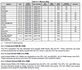
    what is the difference between RAMM0 , RAMM1, RAMLS4567 and RAMGS0 ?

    Thanks for your help

    Damien

  • I now work with interrupts triggered when an RX frame is received.

  • Damien,

    Good to know that you have isolated the root cause of your CN issues.  So as not to create several topics on this thread, i will move it to close.  For additional queries or questions on a different topic,  please post it to the forum so it can be tagged accordingly.

    As to the RAM differences, this is detailed in the TRM as well as in datasheet.  Here is a snippet from the datasheet on the RAM differences:

    Best regards,

    Joseph