Hi All,
I'm laying out a PCB that has a TMS320F28020 on-board and would like to provide an interface for programming/debugging with an Olimex TMS320-XDS100v3.
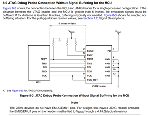
Mapping out signals has been pretty straightforward, but I'm not sure what to do with EMU0 and EMU1 signals. Can anyone point me to some documentation that explains what these signals are for and how they are used?
On a previous design, those XDS100 pins were simply tied to VDD. If they can be helpful in debugging, I may want to use them in the design. I suspect they would be tied to GPIO pins on the processor, but I'm just guessing.
Can anyone help me?
Thanks,
robin