


Other Parts Discussed in Thread: SFRA, CONTROLSUITE
Hi team,
Here're some issues from the customer may need your help:
The DC-AC currently uses an open loop inverting output 50-HZ sinusoidal waveform because during the debug phase, the Vbus bus voltage is powered in series with 4 12-V 7AH, so the bus voltage is 48 V~52 V, and the inverted H-bridge is shown in Figure 1.
The PWM2A drives Q1 through the drive circuit output, the PWM2B drives Q2 through the drive circuit output and the PWM2 drives at 20 KHZ.
The PWM3A drives Q3 through the drive circuit output, the PWM3B drives Q4 through the drive circuit output, and the PWM3 drives at 50HZ.
And the PWM2 and PWM3 match the code of the reference project9(tidm_hv_1ph_dcac project). Because TMS320F28027 this chip does not support floating-point operations, the following code is executed in the PWM2 interrupt:
RAMPGEN_run(&rgen1);
//
// Use the angle value to compute the sine value
//
invSine = sinf((rgen1.out)*6.283185307f);
The execution of the above code program has a significant delay, so the number (1-abs (iinvSine * invModIndex)) is set to 200 elements of the uint16 type, calling the same array each time the zero is passed (ZeroCross). However, following this procedure, the waveform of the first half of each halfshaft (that is, one-fourth of the full cycle at a time of zero crossing) will exhibit an exception (as shown in Figure 2). See Figure 3 for a schematic overview of the H-bridge.
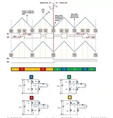
Figure 1
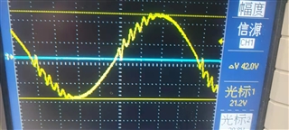
Figure 2
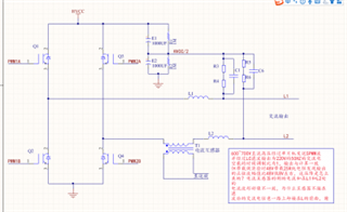
Figure 3
Issues:
1) Why does this scheme have waveform abnormalities when crossing zero, how can it be improved in the program? Note: the code is purely open loop inverting and does not use SFRA and DCL.
2) Does the invSine value conform to SPWM's laws? How is the invSine value generated modulated? Unipolar SPWM or bipolar SPWM?
3) Is there any reference could help when make an inverter? And it would be better with a detailed inverting process and waveform.
Could you help check this case? Thanks.
Best Regards,
Cherry

