This thread has been locked.

If you have a related question, please click the "Ask a related question" button in the top right corner. The newly created question will be automatically linked to this question.

TMS320F280049: TIDA-010054

Part Number: TMS320F280049
Other Parts Discussed in Thread: TIDA-010054

Hi, 

    I would like to confirm one thing TIDA-010054:

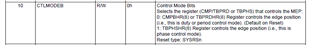
    Are registers CMPAHR, CMPBHR, DBREDHR, DBFEDHR and TBPHSHR are enabled? Only TBPRDHR is disabled?

    Do I think right? Thanks


Zijian

  • It has been a while since i wrote this configuration, here are my notes from the time this was done:

    PWM configuration

    Up-down count mode is used to generate the PWMs for the primary and secondary legs of the dual active bridge. To use the high-resolution PWMs, the PRIM_LEG1_H PWM pulse is centered on the period event and the time base is configured to be up-down count. A complementary pulse with high-resolution dead time is then generated for the complementary switch. Between LEG1 and LEG2, there is a 180-degree phase shift for a full-bridge operation. This is achieved by using the feature on the PWM module to swap the xA and xB output. The PWM frequency for this application is 100Khz. The TBPRD register is set to a value 500 in up-down count mode.

    The duty cycle value is loaded in CMPA register of the EPWM base and is configured to generate 50% duty cycle. The action qualifier module outputs the required action for controlling the PWM output on a compare A event. The global link mechanism on the Type-4 PWM is used to reduce the number of cycles needed to update the registers and enables high-frequency operation. For example, the following code in the DAB_HAL_setupPWM() function links the TBPRD registers for all the PWM Legs.

    Using this linkage, a single write to the PRIM_LEG1 TBPRD register will write the value to PRIM_LEF2, SEC_LEG1, and SEC_LEG2.

    Hi-Resolution Features used :

    • High-Resolution Phase Shift
    • High-Resolution Dead Band
    • High-Resolution Duty → Not available, CTMODEB is set to 1
    • High-Resolution Period → Not available, CTMODEB is set to 1 

    High-Resolution Phase Shift Configuration:

    The PWM pulses of the secondary side are phase-shifted with respect to the PWM pulses of the primary. Controlling the phase shift enables transfer of power between the primary and secondary and vice-versa. The maximum power transferred is very sensitive to the value of phase shift in a Dual Active Bridge. A small series inductor can lead to maximum power transfer at a small value of phase shift. Since the range over which the phase shift is going to be varied is small, and accurate control would require fine increment/decrement steps of phase. The phase control is implemented using Hi-Res (high resolution) feature of F28004x. The function DAB_calculatePWMDutyPeriodPhaseShiftTicks() inside ISR1 calculates the required the required high resolution phase control for both voltage and current mode control. This helps in handling sudden load changes smoothly without producing huge overshoots/transients in the current waveforms.

    For positive and negative phase shift the calculation is done in a slightly different manner to accommodate the hardware implementation of the HRPWM. 

    static inline void DAB_calculatePWMDutyPeriodPhaseShiftTicks(void)
    {
    ...
       //
        // first the phase shift in pu is converter to ns
        // this is done for better debug and user friendliness
        //
        DAB_pwmPhaseShiftPrimSec_ns = DAB_pwmPhaseShiftPrimSec_pu *
                ((float32_t)1.0 / DAB_pwmFrequency_Hz) *
                (1 / ONE_NANO_SEC);
     
        //
        // next this ns is simply converted to ticks
        //
        DAB_pwmPhaseShiftPrimSec_ticks =
                (int32_t)((float32_t)DAB_pwmPhaseShiftPrimSec_ns *
                           DAB_PWMSYSCLOCK_FREQ_HZ * ONE_NANO_SEC *
                           TWO_RAISED_TO_THE_POWER_SIXTEEN) -
                 ((int32_t)2 << 16);
     
        //
        // due to the delay line implementation depending on whether it is
        // a phase delay or an advance we need to adjust the
        // HR phase shift ticks calculations
        //
        if(DAB_pwmPhaseShiftPrimSec_ticks >= 0)
        {
            DAB_phaseSyncPrimToSecCountDirection = EPWM_COUNT_MODE_DOWN_AFTER_SYNC;
     
            //
            // DAB_pwmPhaseShiftPrimSec_ticks has the correct value already
            //
        }
        else
        {
            DAB_phaseSyncPrimToSecCountDirection =  EPWM_COUNT_MODE_UP_AFTER_SYNC;
            DAB_pwmPhaseShiftPrimSec_ticks = DAB_pwmPhaseShiftPrimSec_ticks * -1;
     
            DAB_pwmPhaseShiftPrimSec_HiResticks =  ((uint16_t) 0xFF - ((uint16_t)
                       (DAB_pwmPhaseShiftPrimSec_ticks & 0x0000FFFF)>>8));
     
            DAB_pwmPhaseShiftPrimSec_ticks = ((DAB_pwmPhaseShiftPrimSec_ticks & 0xFFFF0000) + 0x10000) +
                    (DAB_pwmPhaseShiftPrimSec_HiResticks << 8);
        }
    }
    static inline void DAB_HAL_updatePWMDutyPeriodPhaseShift(uint32_t period_ticks,
                                    uint32_t dutyAPrim_ticks,
                                    uint32_t dutyASec_ticks,
                                    uint32_t phaseShiftPrimSec_ticks,
                                    uint16_t phaseShiftPrimSec_direction)
    {
    ...
        EALLOW;
        HWREG(DAB_SEC_LEG1_PWM_BASE + HRPWM_O_TBPHS) = phaseShiftPrimSec_ticks;
        HWREG(DAB_SEC_LEG2_PWM_BASE + HRPWM_O_TBPHS) = phaseShiftPrimSec_ticks;
        EDIS;
    }

    The variable 'DAB_phaseSyncPrimToSecCountDirection' is updated to control the forward mode or reverse mode of power flow.


    Following are the unit tests the code was verified against 

    PWM driver requirements

    Frequency/ Period → fixed, cannot be HRPWM i.e. TBPRD is only regular resolution bits

    Phase shift between primary and secondary can be changes with Hi-resolution 

    Dead-band can be changed with high-resolution

    Duty cycle is fixed at 50%

    Pass criteria for Lab1

    Connect probes on PWM1A (Q1), PWM1B (Q2), PWM3A(Q5) and PWM3B (Q6)

    1A and 1B will be complimentary pair 3A will be in sync with 1A with the specified phase shift, right now the phase shift is controlled by the variable DAB_pwmPhaseShiftPrimSecRef_pu, 

    Check

    1. Frequency is 100kHz 
    2.  Now change phase shift to 0.01 → 500ns, to see more observable phase shift, 

    3. Phase shift matches that specified by the variable on the oscilloscope and Make sure you check for non clock ticks i.e. sub 10ns internals of phase shift to verofy hi-resolution operation. In the below the phase shift is measured using the oscilloscope to be ~500ns for 500ns set point and ~502ns for 502ns set point, small jitter ~1-2ns can be measurement error. 

      Caution: Phase shift is not recommended to be operated beyond 0.45pu


    4. Next change the PWM probes to PWM1A, PWM1B, PWM2A and PWM2B

    verify PWM1A and 2B are in sync and in phase

    verify PWM1B and 2A are in sync and in phase

    5. verify that they remain in sync and phase as the phase shift for sec side PWM is changed. 

    6. Dead time validation

    The value of dead time can be adjusted by modifying the values of the following variables in dab_settings.h

    #define DAB_PRIM_PWM_DEADBAND_RED_NS ((float32_t)300)
    #define DAB_PRIM_PWM_DEADBAND_FED_NS ((float32_t)300)
    #define DAB_SEC_PWM_DEADBAND_RED_NS ((float32_t)300)
    #define DAB_SEC_PWM_DEADBAND_FED_NS ((float32_t)300)

    300ns dead time (raising and falling edges)

  • Thanks a lot. You have corrected my wrong thought that HR duty is enabled. 

  • Hi, Manish:

      As for

    CTLMODEB = 1;

    Then are the following sentences correct? : "The duty HR and period HR can be enabled simutaneously." "Phase HR and duty/period HR cannot be enabled at the same time."

    Waiting for your reply. Thanks.

    Zijian