This thread has been locked.

If you have a related question, please click the "Ask a related question" button in the top right corner. The newly created question will be automatically linked to this question.

TMDSHVMTRINSPIN: Calculation of PI value

Part Number: TMDSHVMTRINSPIN
Other Parts Discussed in Thread: MOTORWARE

Dear team:

The customer uses the formula in the following document to calculate the pI value:

Files\MotorWare\motorware_1_01_00_18\sw\solutions\instaspin_foc\boards\drv8312kit_revD\f28x\f2806xF\src

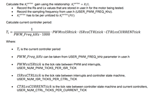
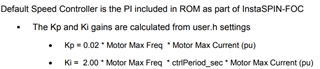
The PI value of the calculated current loop (PWM frequency is 15KHz) is: Ki = 0.03098,Kp = 0.0926

If the PWM frequency used is 20kHz displayed on the GUI interface, the calculation result is: Ki = 0.02324,Kp = 0.2696

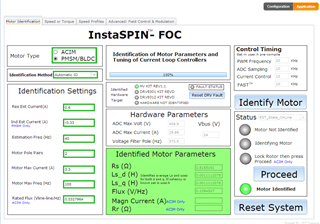
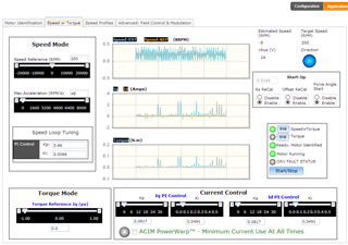
The customer uses GUI to control the motor. After inputting the same parameters on the interface, the identified parameters are inconsistent every time.

1, Excuse me, which document should be used to calculate the pI value?

2, How are the parameters in the GUI determined, such as res EST current, Ind EST current, estimation freq, etc?

Best regards

  • You may take a look at Chapter 11 Tuning Regulators of the InstaSPIN-FOC and InstaSPIN-MOTION User's Guide for the current PI regulator. The speed PI regulator should be not as the description in this guide, you have to refer to the codes in the InstaSPIN lab project.

    https://www.ti.com/lit/spruhj1

    BTW, recommend to run a new motor and debug/tune the lab within CCS. The GUI is used to run a demo for a motor with the known parameters.

    Please follow the lab user's guide  (instaspin_labs.pdf) in the folder below to run the related lab projects and change the parameters in the user.h file. The GUI can't set any control parameters, just to start/stop the motor and set the reference speed for running a motor.

    C:\ti\motorware\motorware_1_01_00_18\docs\labs

  • Hi Yanming:

    Thank you for your reply.

    The customer still has some questions about the bus voltage of the motor:

    If the rated voltage of the customer's motor is 380V, but the input bus voltage is 48V, will the inertia identified by using this low voltage affect the accuracy?

    Best regards

  • Not sure. That depends on the target running speed, seems like the dc bus voltage is not enough.

  • Hi Yanming:

    Today, the customer uploaded his board hardware connection and some expressions window settings and the indicator light display after running lab01b program:

    Do [main] - BS5 and [main] - BS6 on the board need to be connected?

    Any other questions?

  • Please take a look at the guides below to setup the kits.

    qsg_hw_cncd28069miso.pdf

    C:\ti\motorware\motorware_1_01_00_18\docs\boards\control\f2806x\docs

    qsg_hw_hvmtr_r1p1.pdf

    C:\ti\motorware\motorware_1_01_00_18\docs\boards\drive\hvkit_rev1p1\docs