This thread has been locked.

If you have a related question, please click the "Ask a related question" button in the top right corner. The newly created question will be automatically linked to this question.

TMDSHVMTRINSPIN: TMDSHVMTRINSPIN: Universal Motor Control Lab motorVars_M1.speed_Hz is not following the motorVars_M1.speedRef_Hz

Part Number: TMDSHVMTRINSPIN
Other Parts Discussed in Thread: CONTROLSUITE

I am trying to implement Universal Motor Control lab with  own control card  F280025C, own hardware board with 1 hp PMSM motor.

1. In build2, motorVars_M1.speed_Hz is not following the motorVars_M1.speedRef_Hz. 

2. As mentioned in the document spruj26.pdf, I have changed the following parameters according to our motor

                  #define USER_MOTOR1_FREQ_LOW_Hz             (10.0f)         // Hz               // Hz - suggested to set to 10% of rated motor frequency

                  #define USER_MOTOR1_FREQ_HIGH_Hz            (110.0)        // Hz             // Hz - suggested to set to 100% of rated motor frequency

                  #define USER_MOTOR1_VOLT_MIN_V              (10.0f)         // Volt            // Volt - suggested to set to 15% of rated motor voltage

                  #define USER_MOTOR1_VOLT_MAX_V              (70.0f)        // Volt          // Volt - suggested to set to 100% of rated motor voltage

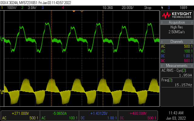
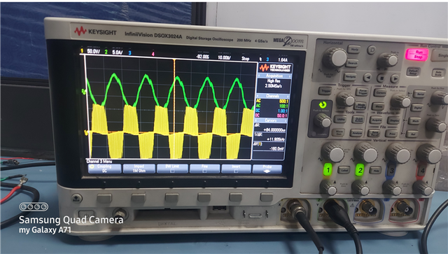
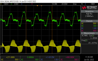
    but current and voltage waveforms obtained are not as provided in the document.

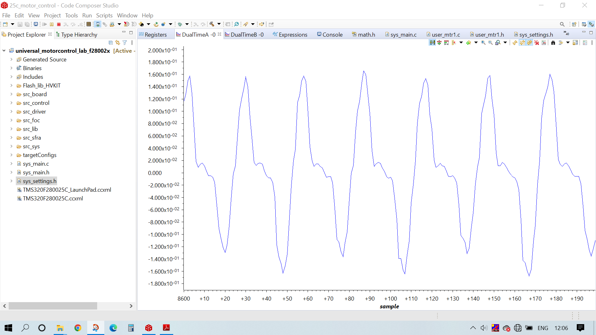
Please look into the following attachments of obtained datalog waveforms and the expression window


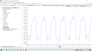
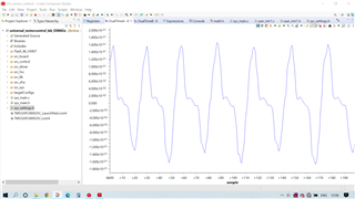
                  datalog voltage waveform                                                                               datalog current waveform


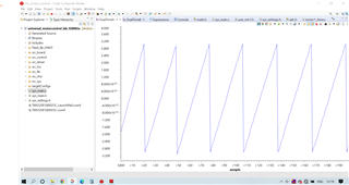
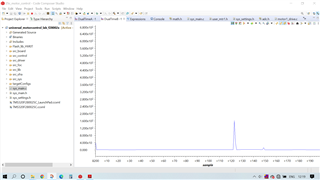
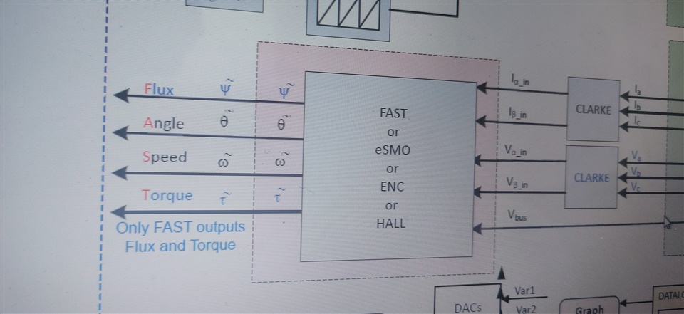
    force angle generator                                                                      Motor rotor angle from  estimator
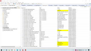
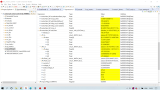
                                                                           expression window

kindly look into this issue.

  • You need to set the right motor parameters like Rs, Ls, Flux, and pole pairs for the estimator in build level 2~4. The motor parameters should be found in its datasheet, or identified in build level 4 if you use a TI EVM kit.

    Keeping tuning the v/f curve as you mentioned above to run the motor smoothly, seems like the motor doesn't run well in build level 2 as the pictures you posted. If the motor runs smoothly, but the waveforms are not similar to the shape shown in lab guide that means the current or voltage sensing circuit are not good.

  • Hi Yanming,

    As you said, I am trying to rectify the voltage and current sensing circuits meanwhile I am confused about the inputs to the clarke transform.

    1. The parameters adcData.I_A  and adcData.V_V values are given as inputs to the clarke_run() function and my doubt is whether these parameters should reflect the actual currents and voltages drawn by the motor..?

    2. And I am using only two current sensors with current gain 1, so i have changed

                                   #define USER_M1_NUM_CURRENT_SENSORS         (2)

                                   #define USER_M1_ADC_FULL_SCALE_CURRENT_A          (3.3f)       in user_mtr1.h

       Do I need to change any other parameters for proper current sensing..?

  • 1. The parameters adcData.I_A  and adcData.V_V values are given as inputs to the clarke_run() function and my doubt is whether these parameters should reflect the actual currents and voltages drawn by the motor..

    Yes, they are motor phase current and voltage.

           #define USER_M1_ADC_FULL_SCALE_CURRENT_A          (3.3f)       in user_mtr1.h

    These three variables are dependent on your hardware board, please set them correctly, you may refer to the lab guide to calculate these three values. You may find a excel sheet in the folder of the Universal Lab that could be useful to do this calculation.

    //! \brief Defines the maximum voltage at the AD converter
    // Full scale voltage of AD converter, not the current voltage
    #define USER_M1_ADC_FULL_SCALE_VOLTAGE_V (409.90f)

    //! \brief Defines the analog voltage filter pole location, Hz
    //!
    #define USER_M1_VOLTAGE_FILTER_POLE_Hz (375.55f)

    //! \brief Defines the maximum current at the AD converter
    #define USER_M1_ADC_FULL_SCALE_CURRENT_A (19.995f)

  • Hi,

    Thank you for the support. I have been trying to implement voltage and current sensing circuits as per the TI EVM kit but the result is not accurate. Can i get the schematic of TI DIGITAL MOTOR CONTROL [R5] EVM kit.  

  • Download and install CONTROLSUITE http://www.ti.com/tool/CONTROLSUITE, and find the hardware design files in the folder as below. The schematic and PCB layout are design with ExpressSCH software. You can also find the .pdf format files.

    C:\ti\controlSUITE\development_kits\HVMotorCtrl+PfcKit_v2.1\~HVMotorCtrl+PFC-HWdevPkg

  • Thank you for the support,

    In the path we have gone through this HVMotorCtrl+PFC-SCH[R1.1]  schematic but compared to the board it is different . we are using this version TI DIGITAL MOTOR CONTROL [R5] EVM kit. This board schematic is not found in CONTROLSUITE.

  • Please refer to the one mentioned above which includes the right phase voltage sensing circuit to support the InstaSPIN/FAST algorithm.

  • Thank you for the support,

    As you said Clarke transform inputs are given the actual current and motor voltages but speed_hz is not following the speed_ref.

    Can you please provide the est_run() and est_getfm_lp_hz() definitions for our clarification.

    Thank you Relaxed

  • 1. est_run() function inputs are given from Clarke voltage and current outputs , speedRef and VDC Bus. Our motor rated voltage is 70v , rated current 8A and we are giving input 110v dc using simulator. Is there any issue with the input supply or should we change any parameter regarding this..?

    2. In spruj26.pdf software block diagram "only FAST outputs flux and torque " is given. What does that mean?

  • Can you please provide the est_run() and est_getfm_lp_hz() definitions for our clarification.

    You can find the definitions in the "est.h", and refer to the example lab to call the functions.

    s there any issue with the input supply or should we change any parameter regarding this..?

    Did you have any opportunity to run a motor with TI EMV kit? As mentioned above, the issue should be from the current/voltage sensing signals on the board, or the motor parameters are not correct, or the build configuration is not selected correctly.

    2. In spruj26.pdf software block diagram "only FAST outputs flux and torque " is given. What does that mean?

    The lab can supports different motor control algorithm, only the FAST has the function to output the estimation Flux and Torque, the other algorithms don't have such function. 

  • can we get est.c file for reference?

  • Hi Yanming,

     In build 2, waveform in datalog are the feedback from motor and our datalog current waveform is reflecting the same as captured by a current probe of oscilloscope. So current sensing is working good. Current drawn by the motor itself is not pure sinusoidal. But I don't think problem is with the motor because when the motor is run in open loop with 28035 controller current waveform is sinusoidal.

    What should be done for pure sinusoidal current waveform..?


    scope and datalog current waveform when run with universal motor control lab

    current waveform with 28035 controller

  • Seems like the motor didn't run well with open-loop, the issue could be from the v/f profile parameters or the inverter. You have to debug the hardware to ensure that the motor can run well as you did with F28035.

    Did you check the input and output signals of the gate driver? And did you verify the phase voltage sampling signals that are necessary for FAST estimator?