This thread has been locked.

If you have a related question, please click the "Ask a related question" button in the top right corner. The newly created question will be automatically linked to this question.

C2000WARE-MOTORCONTROL-SDK: Follow Up - Motor control issues at high current and speed

Part Number: C2000WARE-MOTORCONTROL-SDK
Other Parts Discussed in Thread: MOTORWARE, INA4181

Hello,

We are following up on this thread: https://e2e.ti.com/support/microcontrollers/c2000-microcontrollers-group/c2000/f/c2000-microcontrollers-forum/1055503/c2000ware-motorcontrol-sdk-motor-control-issues-at-high-current-and-speed

We have obtained these values, and there was no change in the issue. We are also seeing other unresolved threads where the same issue seems to persist in the new generation of C2000 microcontrollers running instaspin: https://e2e.ti.com/support/microcontrollers/c2000-microcontrollers-group/c2000/f/c2000-microcontrollers-forum/1076968/tms320f280049c-instaspin-instability-at-high-speed---280049c-drv8353

We have since started using a new generation of C2000 on a validated product that used to use an older generation (no longer available due to chip shortages). This new system, with identical hardware other than the C2000 change, now suffers the same problems. Motor and operating parameters are exactly the same, but now we are seeing instability similar to the aforementioned posts.

  • Could you please provide more information like motor parameters, the maximum current and speed? Some captured current waveform if possible.

  • Hi Yanming,

    To summarize our situation, we have a motor control product based on the F28069M that is able to drive a custom PMSM motor to approximately 2kw. A redesign of the system using the F280025C using a project built off the universal motor control library


    Here are the motor parameters:

    #define USER_MOTOR1_TYPE MOTOR_TYPE_PM

    #define USER_MOTOR1_NUM_POLE_PAIRS (10)

    #define USER_MOTOR1_Rr_Ohm (NULL) //Leave Null

    #define USER_MOTOR1_Rs_Ohm (0.0165843945)

    #define USER_MOTOR1_Ls_d_H (1.03104658e-05)

    #define USER_MOTOR1_Ls_q_H (1.03104658e-05)

    #define USER_MOTOR1_RATED_FLUX_VpHz (0.0195749477)


    Using this motor we are able to drive it up to 2Kw, 8500RPM (141Hz electrical frequency), with Iq ref of approximately 50A. The PWM and ISR frequency is set to 15khz

    I understand that this is a low inductance motor. However it worked perfectly with the F28069M using motorware. When using  MotorControlSDK on a new revision using the F280025C, we can't achieve anywhere close to the same performance. It seems as though the current control loop goes unstable when we try to get past 6000rpm and approximately 15 phase amps.

    I have tried to adjust the USER_M1_EST_FLUX_HF_SF parameter, as suggested in other threads. I tried all the suggested values of 0.12, 0.25, and 1.0, and also tried 0.5 just to check. It did not seem to have an effect on the threshold where the motor control goes unstable.

    Can you please let me know which captures would be useful for you to see what is going on with this system? I will prepare some captures of the phase current at the point where it starts to become unstable.

    Can you please let us know if there is any other difference between the estimator from motorware and the estimator in motorControlSDK? I know that you have mentioned the HF parameter issue, as well as the change from IQ math to floating point. It just really seems as though there is some difference between the two systems.

  • Can you please let me know which captures would be useful for you to see what is going on with this system? I will prepare some captures of the phase current at the point where it starts to become unstable.

    You may try to tune the current and voltage sensing circuit, especially the RC filter at the input of the ADC. Take a look at https://www.ti.com/lit/an/spract6/spract6.pdf and https://www.ti.com/lit/an/spracv0/spracv0.pdf for

      • Information on expected errors from inadequate S+H time
      • More information on how to design the signal conditioning circuits
    Can you please let us know if there is any other difference between the estimator from motorware and the estimator in motorControlSDK? I know that you have mentioned the HF parameter issue, as well as the change from IQ math to floating point. It just really seems as though there is some difference between the two systems.

    Did you enable overmodulation? You may try to disable the overmodulation and limit the "USER_M1_MAX_VS_MAG_PU" to (.057) to see what happens. We are trying to find the root cause for high speed with high current issue on this version of the FAST library, but limit to the test condition, it's difficult to re-appear some cases.

  • Hi Yanming

    Our design uses an ina4181 current sense amplifier and a charge sharing circuit with an Rs of 50ohm and Cs of 150pF. I believe this should result in a minimum settling time of 11 adc clocks at 50MHz. We left the sample time at 14 clock cycles. I can try to tune the charge sharing circuit if you think it would help.

    There are a couple main questions I have that I was hoping you could help shed some light on.

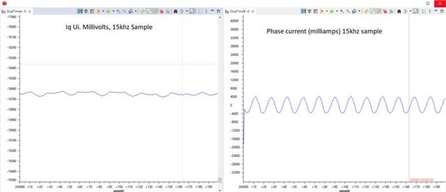
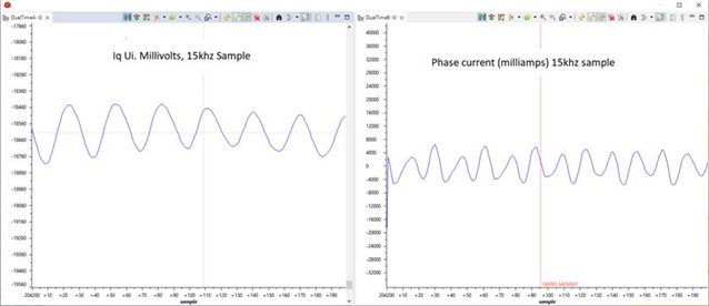
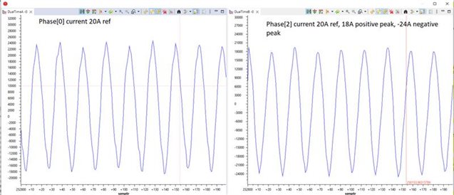
    The main problem is that the appears to be a line past which the Iq and Id current control loops appear to go unstable. This line is a function of both Iq ref and motor speed. I have been testing the system with a dyno and can independently set the Iq ref and the speed. The first test shows what it the operation looks like just before going unstable, in this case at 833Hz (samples are taken each ISR, ISR and PWM rate are at 15khz) and 38A IsSet. The only change to the second test is changing the current reference to 42A. The ripple in the UI increases drastically and the phase current stops being sinosoidal. The current in the right plot is in 10's of milliamps just because it was easier to store as an int16_t. (add picture of what looks stable vs what looks unstable)

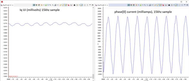
    The second issue might not be the main problem, but it seems as though there is an issue with the PWM waveform being output to the gate drivers. I noticed that during operation, it looks like the Vq output of the Iq control loop had a ripple exactly in phase with the electrical frequency of the motor. 


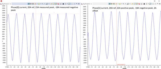
    I proceeded to set the Kp of both PI_Iq and PI_Id to 0 while the dyno was set to a constant speed. I expected the output current to stay relatively constant, but the current measured on each phase seemed to have an offset.

    So far as I can tell, it seems as though the current control loop is responding to this offset and that is causing the ripple seen in the output of the Iq control loop. I believe that these current measurements are accurate, they line up with the current clamp probe measurement taken with an oscilloscope. I can try to get those captures if they would help. Furthermore these currents add to very close to 0 when I make a function to add them together. I can get a plot of that too if it helps.

    I am not sure why there would be such a large offset between the phase currents when being driven with a constant Vq and Vd. The Vabc and corresponding PWM CMP values have exactly matching positive and negative peaks, exactly what would be expected.

    I have not run this test on any system running with an F28069M controller. So far as we could tell this was never an issue on the systems running motorware, but we have not been able to run any system using motorcontrol SDK to high currents and speeds. I understand that you have said that the instaspin estimator is the same between these two versions so I am having a lot of trouble understanding where this difference is coming from. Please let me know if there are any other tests I should run.

    I am not sure if this is helpful, but it does seem like the phase current waveforms often look closer to a triangle wave than a sinusoidal wave when compared to the old motorware systems. I have re identified the motor several times and it lines up with the parameters measured with the old motorware systems. Is there any other parameter that could affect the estimator that could cause this effect?

    Again please let me know if you have any questions or suggestions that might help find the issue. I am trying everything I can think of to isolate what the issue is. Can you confirm that there are Motorcontrol SDK systems that can run large, low inductance drone motors?

    Thanks for your help.

  • 1. Is it possible to improve the PWM and ISR frequency? Like PWM=40kHz, ISR=20kHz

    2. Do you do the offset calibration on each board?

    Can you confirm that there are Motorcontrol SDK systems that can run large, low inductance drone motors?

    Tested this lab on some of the drone motors like 1000Hz/30A, but not the high current one as you used limit to the inverter board and power supply.

  • Hi Yanming

    I tried both of these changes. Its hard to tell but it doesn't seem to have changed much. Using the offset recalc seems to help a bit with the phase current shift at lower speeds, but the speed and current where the instability starts doesn't seem to change. It seems like around 6500RPM and 40A of phase current reference is the limit, but we're hoping to get to 8500RPM and 55A

    Are there any plots of values during operation or oscilloscope captures that might help see what is going wrong?

    At this point, we would really like to know if there are known issues with this new generation of C2000. We have had this motor running perfectly with the previous generation, and are now seeing issues with the new one. We would really appreciate transparency on this matter. As we have seen other unresolved posts/issues similar to our own, it would be good to know whether we may not fix this issue even if we invest considerable resources.

  • What's the maximum dc bus voltage for the motor and inverter board? What's the maximum electrical frequency of the motor? Or the pole pairs of the motor?

    Does the 55A mean the RMS value of the motor phase current? Or the peak current?

  • Hi Yanming,

    We have attached an encoder to our motor in order to get the absolute position of our motor. We then indexed it to phase A such that it should give the angle of the motor BEMF relative to phase A. We have then spun up the motor and compared the output angle of the estimator to the angle received from the encoder.

    From this we were able to find that the angle output by the estimator is not accurate (this is even after the compensation angle being added to it). We did some tests and found that this error increased under two scenarios:

    1. As the speed increased and the current kept the same (the motor is on a dyno). We also found that this increase was linear.
    2. As the current was increased and the speed kept the same. Again we found this was linear.

    From this we were able to come up with a formula to make our own angle compensation and apply it to the output from the estimator. This appears to have fixed out problem as we are now able to get up to much higher speeds. Our formula has the format of angle_comp = x*speed_hz+y*phaseCurrent+constant

    This matches our previous observations that it was a combination of both speed and phase current that was causing issues since these are the factors that cause the most error in the angle.

    Our question now is what could be causing the estimator to be giving these incorrect angles? Specifically something that would get affected by both speed and phase current. We did not see this issue on previous versions of instaspin while running the same inductance and resistance parameters.

    One thing we are trying is changing the inductance while the motor is running (not something we had to do before). We have tried using the functions EST_setLs_dq_H, EST_setLs_d_H, EST_setLs_q_H. They have no effect and the angle estimation. So can you tell us the correct way of changing the motor parameters on the fly?

  • Our question now is what could be causing the estimator to be giving these incorrect angles?

    The issue could be from the motor model is not accuray for the FAST since some of the motor parameters are variable with current, especially, the Lq will change obviously. I am trying to identify the root cause and find a solution, but it could be not easy to solve it in a short time. I would like to let you know if have any update. You may have to calibrate the estimation angle first by using the angle compensation method.

    They have no effect and the angle estimation. So can you tell us the correct way of changing the motor parameters on the fly?

    You may just call EST_setLs_q_H() to adjust the Lq. The changes of the Ld could be very small with current. The major issue could be from the changes of the Flux.

  • I thought that the flux was measured and updated by FAST. If the flux changes significantly during operation is there anything that our application can do to help compensate for this? Can the rated flux parameter be adjusted during operation?

    With regards to EST_setLs_q_H() I'm not sure if I'm doing something wrong but it seems like it doesn't actually update in the estimator. I call EST_setLs_q_H(obj->estHandle, newInductance), and I can see that EST_getLs_q_H(obj->estHandle) returns the newInductance value. However it does not seem to have any effect whatsoever on the estimator. I can set the inductance to 0 and it runs exactly how it ran with the inductance set with USER_MOTOR1_Ls_q_H. Is there another function that is constantly resetting the inductance back to USER_MOTOR1_Ls_q_H that I could be missing? Or is there any chance that there is an issue with the EST_getLs_q_H() function?

  • Seems like we can change some of the parameters for the flux estimation as the HF patch library. I need to go through the library and setup a testing platform to verify it, which could need some time to do this.

    There is only EST_getLs_q_H() to set/update the Lq. 

  • Is there any possible way that these values could be compared against the old motorware instaspin parameters? I am sorry if this is beating a dead head horse but it really seems like there is some kind of change in the estimator between motorware and motorcontrolSDK.

    Would it be possible for me to try to modify any of these other parameters so that I could see if any changes improve the estimator accuracy on our setup?  Would you be able to provide the offset from estHandle to any of these parameters so that I can update them in operation? I can try to adjust any of them just to see if the error of the estimator is reduced. Maybe that could help you isolate the issue.

     Could you also provide any details about the EST_setLs_q_H() function? It seems to update the inductance parameter stored in the estimator because it reads back the correct new inductance value with the EST_getLs_q_H() function. Is it possible that there are other internal parameters or coefficients in the estimator are derived from the inductance value that are not updated when EST_setLs_q_H()  is called? It really seems like adjusting the inductance using EST_setLs_q_H()  has absolutely no effect on the behaviour of the estimator. Would it be possible to use the EST_setParams() function during operation to try to change the inductance?

  • Both fixed-point version on F2802x/06 and floating-point on F28002x/004x use the same mathematics model, just design the algorithm code with SI format for floating-point version and PU format for fixed-point version. It's difficult to compare the parameters between these two versions since there are a lot of parameters with different format. But I believe that the control parameters should be totally the same on these versions since using the same calculation equations.

    We need to find the root cause and know what parameters need to be changed that could need some time.

    The EST_setLs_q_H() will set the Lq to a control parameter directly. Don't need to call EST_setParams() to reset all of the control parameters.

  • Hi Yanming,

    If the math between the two systems is identical, why would the new estimator not be able to perform accurately when the old one was able to? Are these parameters you are mentioning keeping the algorithm from operating correctly?

    Also, we realize this is supposed to be the case with EST_setLs_q_H(), but modifying this variable is having absolutely no effect on the output. We can change the value to 0, for example, and nothing happens when the motor is running.

  • The PU format can achieve the same resolution between the full range with the same control parameters like the gains of the PI regulator. But the floating-point with SI format will limit the supporting current range to get the same resolution. You may try to use the different gains of the current and speed regulators at low or high speed/current.

    I tested a drone motor that runs well up to 1000Hz (electrical frequency) with 100A (peak current), you may try to change the gains as mentioned. 

  • Can you please elaborate on how it is limiting the current range. What is this limit based on? Is it internal to the estimator or is there a spot in code we can look at to understand it? How does changing the gains help with this limit?

  • Sorry for confusing you, the floating-point doesn't have current limitation. Just mean the calculation resolution will be different at low current and high current with floating point.

    You may try to use large gains for low current and low speed, and small gains for high current and high speed.

  • Hi Yanming,

    Just so we understand, how will improving these gains improve the estimator's output?

    We are certain that the estimator's output is what is causing the issue. We have validated this both in terms of observing the position with the encoder, and by demonstrating that correcting this error using an external function is improving performance. How does modifying gains improve the estimator's accuracy?

  • The gains can't improve the estimator's accuracy, but changing the gain may improve the current response and reduce the impact from the estimator. Also, you may try to tune the objUser->angleDelayed_sf_sec to change the compensation angle.

    // compute angle with delay compensation
    obj->angleDelta_rad =
    objUser->angleDelayed_sf_sec * obj->estOutputData.fm_lp_rps;

    obj->angleEST_rad =
    MATH_incrAngle(obj->estOutputData.angle_rad, obj->angleDelta_rad);

  • We are certain that the estimator's output is what is causing the issue.

    That's no surprise since the ePWM ADC SOCA trigger source (hal.c) only uses one SOCA one CMPD and often 3 different ADC peripheral channels. The three ADC peripherals ADC-A,B,C Clarke position inputs are all using the same SOCn seemingly with drifting of current angles inside each id/iq sector. As motor speed increases so does the mock inner ld/lq sector drift go hand in hand. The duty cycle of each ePWM generator output even being loaded via shadow updates becomes shaky motor flux crash seems inevitable.

    Last week we could not get x49c (hal.c) ePWM module configuration (for loop[cnt]) to configure 3 SOCA trigger sources. Ideally have individual CMPD counting for Instaspin decimation time with 3 ADC triggers for both Clarke channel inputs. That would seemingly tighten EOC pulse times for SOC samples.

    We also saw better electrical response via simple shadow loads versus jamming generator reloads (direct load) at higher rotor speed with less harmonic distortion without any other modifications. Please let the forum know if you have any better high speed current control with shadow loading the generator periods. In general it has been frowned upon to use direct period loading due to the generator updates not being global. Also configured Master/Slave sync mode per the TRM, the generator sync mode is never elaborated as being POR default x49c ePWM type 4 module.

    The ePWM module should be able to configure and trigger each ADC peripheral via individual CMPD counts. With ADCA holding the highest ePIE core priority (PIEIER) group 1. ADCB, ADCC lower priority respectively see TRM section 3.5.6 Table 3-5.

  • Hi Mick,

    As conversion, please share the hardware design files with me. Let's close this thread first.

  • Yanming,

    We have not heard from your team in some time after taking this offline. Since then, we have fabricated hardware in which the only difference is the C2000 microcontroller. The F280025 does not work, the F28069M works perfectly.

    It seems clear at this point, based on the testing we have performed, that the new generation of floating point controller simply does not work as advertised. Can we have some transparency on the issue, and what can be done?

  • . The F280025 does not work, the F28069M works perfectly.

    Curious if the hardware configurations via driverlib calls have anything to do with that issue, x69 verses x25. For example, x49c I changed MCSDK(FOC) PWM configuration to use trigger generator mode versus interrupt trigger mode for EPWM SOCA driving ADC EOC pulses. Such required for mainISR() IRQ handling and Instaspin decimation ticks >3 counts I tested up to 10 ticks.

    Oddly the MCSDK interrupt trigger mode had disabled EPWM interrupts contrary of intended module purpose, See x25 TRM Event-Trigger Submodule section. The module now acts as a pulse generator for SOCA triggering ADC samples EOC interrupts of mainISR(). Small change to EPWM module configuration to use default shadow loads CMPA rather than direct hard loading, now acts as double shadow buffer, default mode. The default mode x49c EPWM is shadow loading CMPA, CMPD unless being forced into direct loading. Likely the same register changes for x25 MCU.

    // set the period load mode quiet shadow loading
    EPWM_setPeriodLoadMode(obj->pwmHandle[cnt], EPWM_PERIOD_SHADOW_LOAD); //EPWM_PERIOD_DIRECT_LOAD

    /* set the ADC event count trigger value */
    EPWM_setADCTriggerEventCountInitValue(obj->pwmHandle[0], EPWM_SOC_A, numPWMTicksPerISRTick);
    //EPWM_setInterruptEventCount(obj->pwmHandle[0], numPWMTicksPerISRTick);

    Yet what seems to be throwing a wrench into MotorVars.speedHz (6 pole Nidec SPM), around 2500 RPM global updates being called returning from ISR into ~flagEnableSys while loop CPU time domain. Also noticed CCS debug java script MotorVars.speedHz ~.speedKM remained zero's only updating after returning from mainISR(), roughly first 300ms of 25µs decimation periods, @20KHz inverter modulation. That first return to while enable loop causes a hiccup in commutation, often throws motor into crash or unstable magnetic condition or it progresses 2500 up to 5400 RPM (250Hz) for motor rated 10KRPM 20VDC. A handheld laser reflective tape check of rotor shaft speed indicated MotorVars.speedKM was lower by roughly 2000 RPM. 

  • In the above wrench throwing case a major problem with maintaining high speed stability was partly due to user.h default number of speed ticks (10). It seems 250µs speed tick (10) was to slow for mainISR() decimation time of 25µs active ISR execution time, 3 PWM ticks producing 150µs pulse width including 25µs ISR execution time.  Also (10) speed ticks is the default MCSDK v3.1 - v4.0.

    USER_NUM_ISR_TICKS_PER_SPEED_TICK       (5)

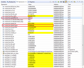
  • Also discovered MCSDK MotorVars.speed_Hz does not concur with actual rotor speed, MotorVars.speed_krpm. Checking CCS debug calculation via typical formula to convert Hertz to RPM produces much lower value of the actual rotor speed.

    The other tweak to hal.c sets EPWM Master Slave phase shift sync mode with both slaves (shift load enabled) phase angle set 0 and comparator shadow double buffers, master load phase shift angle disabled. The x49c EPWM generators are type 4, seemingly the same for x25 MCU. Direct period loading of PWM generator period as used for motor commutation is known to cause electrical glitches in the inverter output, shadow period loading is wise. BTW the below capture PWM triggered ISR is 6.6KHz (150µs 3 PWM ticks) 25µs ISR time at 20KHz modulation.

    Tweaking labs.h global update to match laser checked rotor speed, value (91.0) comes closer laser measured rotor speed 8.1 Krpm. Calculating rotor speed 265Hz using typical math formula renders incorrect speed 5300 RPM. That being said the engineer has to use laser to check actual rotor speed, likely differs for the actual pole pairs count. Oddly the estimator returned frequency requires to add 90Hz into Motorvars_speed_Hz for the pole pairs formula to match Krpm of laser measured rotor speed.

    motorVars.speed_Hz = EST_getFm_lp_Hz(estHandle); 

      motorVars.speed_krpm = motorVars.speed_Hz * (91.0 / 1000.0 / USER_MOTOR_NUM_POLE_PAIRS); 

  • Hi Mick,

    As replied to you before. The only difference between the F28069M and F280025C is that the SI format is using on F280025C, so that the accuracy could be different at high speed and high-current. I am trying to repeat this issue in our lab to find a solution.

  • Let's close this thread first since we need to take some time to have a test to analysis and solve this issue.