This thread has been locked.

If you have a related question, please click the "Ask a related question" button in the top right corner. The newly created question will be automatically linked to this question.

TMS320F28335: Hardware compatibiity of TMS320F28335 controlCARD and TMDSCNCD28035ISO control card

Part Number: TMS320F28335
Other Parts Discussed in Thread: TMDSCNCD28035ISO, , C2000WARE, TMDSCNCD28335

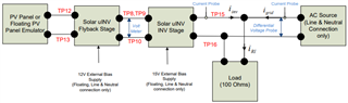
I have purchase TI Solar Micro-inverter Reference Design, this design uses C2000 Solar Micro Inverter EVM kit where TMDSCNCD28035ISO control card is to be used with the base board.

I wish to use TMS320F28335 controlCARD instead and insert this control card into the base board. Then re-do the software again for control of this Solar Micro Inverter in order to fully

understand how to do this for 28335 MCU. Is it possible ? My question is TMS320F28335 pin compatible with TMDSCNCD28035ISO from hardware point of view, such that I can just swap it out.

I understand that I would need to change memory maps, cmd files etc but can re-use some parts of existing code.

Just like to confirm it before I try it out.  Thanks and regards

  • KY,

    These controlCARD are very similar in resources. The F28335 controlCARD does not have an integrated Emulator. You may need to workaround this issue, Perhaps you can program using a docking station and run from flash after connecting to the solar kit.

    Secondly, to confirm if all of the needed resources are available at the DIMM connector you can look at the DIMM maps. These are included in C2000Ware:

    C:\ti\c2000\C2000Ware_4_01_00_00\boards\controlCARDs\TMDSCNCD28335

    C:\ti\c2000\C2000Ware_4_01_00_00\boards\controlCARDs\TMDSCNCD28035ISO

    I don't know exactly what features are used in that kit, but the 03x and 33x series are quite similar, so I expect porting to be a reasonably simple task.

    Regards,
    Cody 

  • Thank you for your confirmation. I did also purchase TI 28335 Experimenter's Kit, that comes with docking station. Your advice solves my issue.

    Sorry but I have one additional related question to this TI Solar-Microinverter Reference Design Board. Currently I am going through the user manual to see the setup used for characterization of this board. In all the setups, as shown in diagram below:

    For the aux. power supplies, the PV emulator equipment and AC Source equipment, the manual stress need to use (Line & Neutral Connection only), as shown. Most, in fact all the equipments in my Lab is wired (single phase) with Line, Neutral and Ground (my country is 230VAC single phase).

    Can you elaborate what is the safety concern here in more detail ? Since I am new to power electronics, safety is my top concern too.

  • Your post is being reassigned to the owner of this development kit.

    Regards,
    Cody 

  • Hi,

    It looks like the suggested test setup tries to avoid creating any ground loop from dc P/S, ac P/S, and dc bias P/S.

    Also, as all P/Ss are floated, don't touch any equipment while you are running the test.

    Best,

    John

  • Thanks for the reply. I have another question related to this solar micro-inverter development kit. In a lot of the test setups shown in the user guide, TI uses either a 100 ohm or 200 ohm or 1K ohm resistor (with high power rating like 500W) as the load. What is the main reason for this ? Is it possible to replace these resistor loads using an AC Load equipment instead ?

  • Hi,

    If you have a grid simulator that consumes the output power of the solar inverter, you can simply build a test setup with that.

    AC source + resistive load in the block diagram was proposed to emulate a grid simulator. The ac source provides the ac voltage information (freq, magnitude) to the solar inverter and the output of the solar inverter is consumed by the resistor and it makes sure the output of the inverter does not transfer to the ac source.

    Best,

    John