


Part Number: TMDSSOLARUINVKIT
Hi Team,
My customer run into a problem using the Texas Instruments Development Board TMDSSOLARUINVKIT and would like to seek for your assistance on this matter, please see details below.
We followed the steps in the user guide (https://www.ti.com/lit/ug/tidu405b/tidu405b.pdf?ts=1654046656762&ref_url=https%253A%252F%252Fwww.ti.com%252Ftool%252FTMDSSOLARUINVKIT)
And tried out the different Builds under chapter 6. Everything worked fine till BUILD = 3 (chapter 6.3.2). Since we live in Germany, we changed the GRID_FREQ to 50 in SolarMicroInv-Settings.h
and connected the inverter output to the 230V grid with a 200 Ohms resistor. The 200 Ohm load is also based on the suggestion in C2000 Solar Micro Inverter QSG.
Our setup is also shown in the following image.
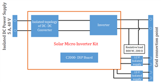
When we turned on the inverter by setting Gui_InvStart to 1 (chapter 6.3.2.4 point 6) the fuse is blown. Also, the daughter card is not getting connected to the CCS as it was easily getting connected previously. Can someone guide us with a solution to the problem? Our connection and all other steps was based on the user guide and the related documents to Solar Micro Inverter kit.
And tried out the different Builds under chapter 6. Everything worked fine till BUILD = 3 (chapter 6.3.2). Since we live in Germany, we changed the GRID_FREQ to 50 in SolarMicroInv-Settings.h
and connected the inverter output to the 230V grid with a 200 Ohms resistor. The 200 Ohm load is also based on the suggestion in C2000 Solar Micro Inverter QSG.
Our setup is also shown in the following image.
When we turned on the inverter by setting Gui_InvStart to 1 (chapter 6.3.2.4 point 6) the fuse is blown. Also, the daughter card is not getting connected to the CCS as it was easily getting connected previously. Can someone guide us with a solution to the problem? Our connection and all other steps was based on the user guide and the related documents to Solar Micro Inverter kit.
Thanks.
Regards,
May
May
