This thread has been locked.

If you have a related question, please click the "Ask a related question" button in the top right corner. The newly created question will be automatically linked to this question.

C2000WARE-MOTORCONTROL-SDK: TMS320F28388D

Part Number: C2000WARE-MOTORCONTROL-SDK
Other Parts Discussed in Thread: TMS320F28388D

Hi,

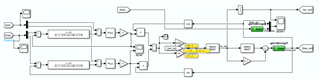
I have a costumed deigned inverter with TMS320F28388D and a low inductance (28.5uH per phase), high speed (120,000RPM) PMSM motor. I am going to implement the sensor-less FOC on this board. I have implemented I/F control based on the following block digram

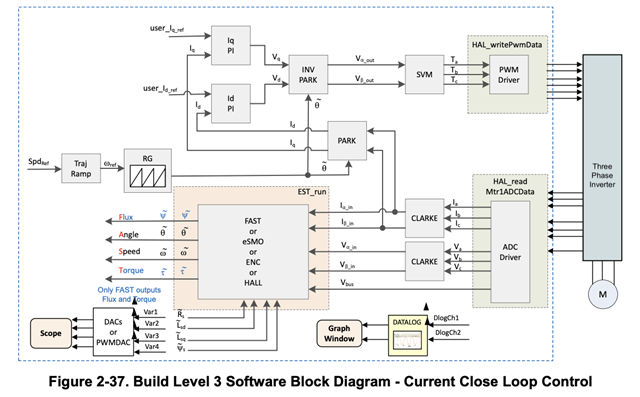
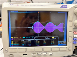
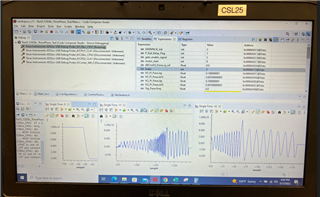
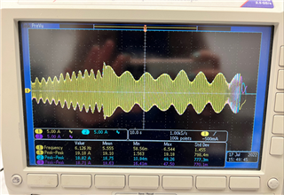
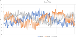
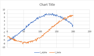
By applying 0A to Id_ref and 5A to Iq_ref, the motor gets started. However, I expect to see the iq and id merging to their dc reference value, I see that the iq and id currents change like a sinusoidal waveform. my trajectory is a frequency function of time as (f= alpha * t^2), where alpha is equal to 0.5. What changes I should make to current controllers' kp and ki to have a nice id and iq following their references; currently, the kp =0.1, ki = 3.125., PWM frequency = 50kHz, and interrupt frequency = 32250Hz.

Thanks in advance,

  • I wanted to add that my real speed falls behind the trajectory function that I designed. So the motor's real speed is less than what I expect. For example, I set the max frequency of my trajectory function on 5Hz, while the maximum speed is different that that. 
    Moreover, I have one question here that I think might solve some issue:

    If my PWM frequency is 50kHz, how much should I assign for my current sampling rate and control loop frequency?
    If I consider control loop to be 8kHz and current sampling 5kHz. Can I get a better response?
    In general, how should I consider the control loop and current sampling frequencies?

  • Hi Mahshid,

    Thanks for reaching out on the E2E forums. Our sensorless FOC expert is out of office this week. Please expect a reply early next week

    Regards,

    Peter

  • What current sensor are you using on your hardware board? What build level are you using to run the motor? Do you set the correct motor parameters in user_mtr1.h, such as Rs, Ls, Flux and Pole pairs? Could you please post the schematic of the hardware, the user_mtr1.h  and the spec. of the motor? That could help us to understand your questions.

    BTW, the I/F open-loop is just used for hardware verification, is not suitable for running the motor at high speed and with heavy load.

  • Hi Yanming,

    The current sensor is "HO 150-NP-0100". I actually have written my own code based on the driverlib examples and libraries. I am reading the phase currents and phase voltages. But the voltage reading is a bit different than the HVKIT schematic as follows:


    The hardware schematic includes different files and to avoid complication, I just attached a part of the sketch. 
    I am running the motor at no-load. and I am trying to figure out my sensor-less method. I used the I-F start-up method to start the motor running. Iq-ref is set to 5A and Id_ref =0 to make the motor start running. Here are some pictures from this test:
    These are the three-phase currents, while there is a sinusoidal ripple on the Iq (which is generated using Park transformation). The sinusoidal ripple of Iq is reflected on speed and Iabc phase currents.

    From Left to Right:

    Trajectory refrence Speed, Iq, Id. As I noticed, the average of Iq is zero and the average of Iq is almost I_qref.

    Here is another picture from phase currents waveforms, where Ki of current controllers (PI controllers) has decreased after a while. By decreasing the Ki, the current regulation gets slower, but there are still big variations. When I did the test using HVkit, Iq could follow the reference very well. However, in my own code, there is this variation. 

    This board is designed for high voltage (500V) and high current (100A). But, this test has been done on 130V and Iq-ref =5A. 

    Are these readings normal due to the fact that the sensor reading design for the high current?

    Moreover, I have collected data on phase voltages (as I described earlier, they are generated using a virtual ground). The data of the phase voltage seems as follows:

    As you see, the phase voltage data are very noisy. What do you suggest to have a better phase voltage reading as Vabc is used in my observer?

    This is while my Alpha beta current (or phase currents are nice and sinusoidal)

    I have another question regarding the observer:
    I found this method in one of TI's workshops from this link:

    Motor control advancements: FOC with AC induction motors, IPM motors, sensorless FOC and observers | TI.com Video

    I simulated this method and it works in the simulation, but in the experiment, the speed is hardly following the reference. I just supposed that might be due to the high noisy data that I am using for phase voltages Va, Vb, and Vc.

    I truly appreciate your help

  • As you mentioned, you should make sure that the current and voltage sensing signals are good first. And then ensure that the estimation angle and speed are right. If not, you have to check and verify the sensing circuit and your own code on the observer, the hardware scaling or motor parameters. That's all we can provide the suggestion to you.