Other Parts Discussed in Thread: TMDSCNCD28379D, LAUNCHXL-F280025C, CONTROLSUITE, C2000WARE-MOTORCONTROL-SDK, C2000WARE, TMDSHVMTRINSPIN
I am working to control BLDC currently working my way through the TMDXIDDK379D, which has 6 build levels. I am on build level 3, First two build levels are completed successfully. In level 3 which asks you to adjust IdTesting, Iqtesting and speedref (ref doc : Quick Response Control of PMSM Using Fast Current Loop) The default current value that would trip this flag is set to 8A, IdTesting = 0 , IqTesting = 0.03, and Speedref = 0.3 had been set.
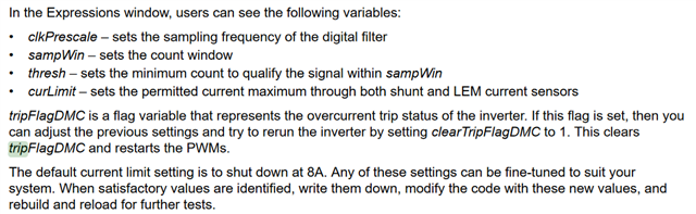
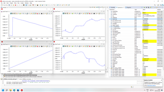
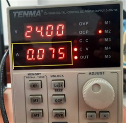
My problem in build level 3 is TripFlagDMC triggers shutdown when i turn motor variable "runmotor' to motor run. but the current draw from the power supply is around 1A, well below the threshold of 8A.
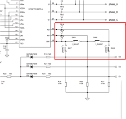
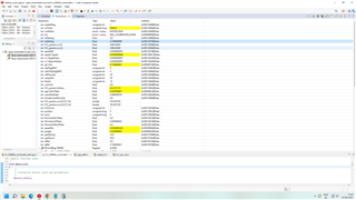
I don't understand what would cause this flag to trigger, and I cant find an expression to monitor the LEM current sense module.
1. Controller board- TMS320F280049C
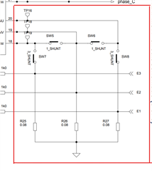
2 Inverter board - ST Evaluation Board (STEVAL-IPM07F)
3. Motor - BLDC - DPN57BLS94.004
Thank you