This thread has been locked.

If you have a related question, please click the "Ask a related question" button in the top right corner. The newly created question will be automatically linked to this question.

LAUNCHXL-F280025C: Voltage Offset Fault

Part Number: LAUNCHXL-F280025C
Other Parts Discussed in Thread: C2000WARE, BOOSTXL-DRV8323RS, DAC128S085EVM

Hello,

We are running the LAUNCHXL-F280025C + BOOSTXL-DRV8323RS with a BLDC along with C2000Ware 4.01.00.00 & MotorControl SDK 4.00.00.00

While running Level 1 in the "universal_motorcontrol_lab_f28002x" project we are getting a voltage offset fault.  Not sure how this is happening as Level 1 doesn't even have the motor connected and everything is "stock" with no modifications straight out of the box other than the  steps required in the document to setup the two boards together.

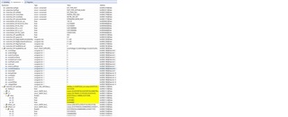
See below data with offsets and faults.  The ADC Voltage values are in the 20's.  From what I understand they should be near zero and I assume this is what is throwing the fault?  What's interesting is that when I manually clear the error and force the system to run the ADC voltage values go to ~ zero.

Any thoughts?

  • Please take a look at the lab guide and follow it to connect the kits. Make sure that the related switches are set correctly on LAUNCHXL-F280025C, and the connection is as below shown in the lab guide. Universal Project and Lab User’s Guide: https://www.ti.com/lit/spruj26


    • For more details about the BOOSTXL-DRV8323RS, see the User's Guide for the EVM.

    • Make sure that the following items are completed as described below, and then connect the BOOSTXLDRV8323RS

    to J1/J3 and J4/J2 of the LAUNCHXL-F280025C as shown in Figure 2-7.

    – Populate C9, C10, and C11 with a 47nF capacitor.

    – Bend J3-29 and J3-30 of the LAUNCHXL-F280025C90 degrees so that they are not connected to the

    BOOSTXL-DRV8323RS as shown in Figure 2-5.

    – If using the DAC128S085EVM board, bend J5-42 of the LAUNCHXL-F280025C 90 degrees to avoid

    connecting that pin to the DAC128S085EVM board. This EVM board is only used for debugging purposes

    to monitor various software variables.

    – Use a jumper wire to connect J3-29 of the LAUNCHXL-F280025C to J3-11 of the BOOSTXL-DRV8323RS

    if the potentiometer functionality is desired to be used on the BOOSTXL-DRV8323RS for setting the

    reference speed.


    Please make sure that the switches are set correctly as shown in lab guide as below also, especially the S2.

    • Install jumpers on JP1, JP2, JP3 and J101 for the power supply and debug JTAG. And jumpers on JP8 for the power supply of DAC128S board if used.
    • For S2, position the SEL1 (LEFT) switch UP (1) to route GPIO28 and GPIO29 to the BoosterPack connector, and position the SEL2 (RIGHT) switch UP (1) to rout GPIO16 and GPIO17 to the virtual COM port of the XDS110 debugger.
    • For S3, position the SEL1(LEFT) switch DOWN to pull GPIO24 low to logic 0, and position the SEL2(RIGHT) switch UP to pull GPIO32 high to logic 1 to put the F280025C into wait boot mode for reducing the risk of connectivity issues or a previous loaded code execution.
    • For S4, set S4 to DOWN (on), GPIO32 and GPIO33 are routed to the CAN transceiver to J14 CAN interface if the pre-define symbols "CMD_CAN_EN" is set in project properties.
    • For S5, position the SEL1(LEFT) switch DOWN to route GPIO44/37/43 to eQEP1 for the encoder interface on J12, and position the SEL2 (RIGHT) switch DOWN to route GPIO14/25/26 to eQEP2 for the Hall sensor interface on J13.

    You may take a look at the links below that have similar questions as yours.

    https://e2e.ti.com/support/microcontrollers/c2000-microcontrollers-group/c2000/f/c2000-microcontrollers-forum/1111505/tms320f280025c-sdk_4-universal_lab-offsets-look-wrong/4121504#4121504

    https://e2e.ti.com/support/motor-drivers-group/motor-drivers/f/motor-drivers-forum/1099773/drv8343s-q1evm-f280025-with-drv8343s-sample-project-for-sensorless-bldc-motor-control-most-suitable-foc-or-trapezodal-algrathrm/4147499#4147499