Other Parts Discussed in Thread: C2000WARE, TIDA-00080, CDCE906
Hello.
I have investigated the module, SDFM, on TMS320F28379D.
First I investigated SDFM with 280049c because it has many examples in c2000ware.
With those examples, I used own epwm to make a clock up to 20MHz for SDFM.
It worked, and I could see the filterresult on CCS debug window.
My final goal is to evaluate TIDA-00080 reference design to use SDFM with TMS320F278379D.
In this design, CDCE906 has been used as a clock generator for the SDFM, not the epwm.
I successfully programmed the CDCE906 to make the 20MHz clock for the SDFM
By using that clock signal, I could see the data stream from the AMC1306.
The figure below is the clock to and data stream signal from AMC1306.
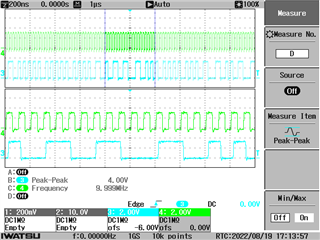
With those signal, I would like to get and see the filter result data from SDFM on CCS debug window.
But I could get the flag data, MFx is set for those signals.
Here are the points that I checked.
1. I could see the proper binary data from GPBDAT.GPIO48/49 which is dedicated to SD-D1, SD-C1.
So I'm sure the clock signal and data stream signal are well delivered to SD-C1 and SD-D1 respectively.
2. I disabled the MFx interrupt. but still, AFx flag is not set.
3. PIEIER5.INTx9 is set as I coded, but PIEIFR5.INTx9 remain '0' state.
From those checkpoints, I thought SDFM interrupt was not working properly and that was the problem.
I could find the cause of the MFx interrupt represented on the Technical reference manual for 28379D.
Page 1818, "Modulator failures (MFx) are generated when SD-Cx goes missing. The modulator clock is considered
missing if SD-Cx does not toggle for 64-SYSCLKs."
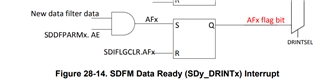
and "When the primary filter is ready with a new filter data, the AFx event is generated. AFx events from any of
the four primary filter modules can be configured to trigger a CPU interrupt."
So, in my case SD-Cx is not missing I think because I could see the value on a dedicated GPIO port.
But I think there is a problem with "not toggle for 64-SYSCLKs"
while using ePWM, PWM clock signals free runs and is synchronized with SYSCLKs.
But I have no idea about the external clock signal.
In summary, my questions are as below.
while using an external clock signal for SDFM (in my case using CDCE906, clock synthesizer)
1. What should I configure to make my SD-Cx toggle for 64-SYSCLKs as explained in the manual to set the flag,MFx, "0'?
2. What makes the MCU indicates the SDFM data is ready to make AFx event generation?
I attached the code below. code is originally from the c2000ware folder, and I configured something.
(I tried to disabled the MFx and enabled)
Thank you for your further help.
Regards.
//###########################################################################
//
// FILE:   sdfm_ex1_filters.c
//
// TITLE:  SDFM Filter sync CPU Example.
//
//! \addtogroup driver_example_list
//! <h1> SDFM Filter Sync CPU</h1>
//!
//! In this example, SDFM filter data is read by CPU in SDFM ISR routine. The
//! SDFM configuration is shown below:
//!  -  SDFM used in this example - SDFM1
//!  -  Input control mode selected - MODE0
//!  -  Comparator settings
//!       - Sinc3 filter selected
//!       - OSR = 32
//!       - HLT = 0x7FFF (Higher threshold setting)
//!       - LLT  = 0x0000(Lower threshold setting)
//!  -  Data filter settings
//!      - All the 4 filter modules enabled
//!      - Sinc3 filter selected
//!      - OSR = 128
//!      - All the 4 filters are synchronized by using MFE
//!       (Master Filter enable bit)
//!      - Filter output represented in 16 bit format
//!      - In order to convert 25 bit Data filter
//!        into 16 bit format user needs to right shift by 8 bits for
//!        Sinc3 filter with OSR = 128
//!  - Interrupt module settings for SDFM filter
//!      - All the 4 higher threshold comparator interrupts disabled
//!      - All the 4 lower threshold comparator interrupts disabled
//!      - All the 4 modulator failure interrupts disabled
//!      - All the 4 filter will generate interrupt when a new filter data
//!        is available.
//!
//
//###########################################################################
//
// $Release Date: $
// $Copyright:
// Copyright (C) 2013-2022 Texas Instruments Incorporated - http://www.ti.com/
//
// Redistribution and use in source and binary forms, with or without
// modification, are permitted provided that the following conditions
// are met:
//
//   Redistributions of source code must retain the above copyright
//   notice, this list of conditions and the following disclaimer.
//
//   Redistributions in binary form must reproduce the above copyright
//   notice, this list of conditions and the following disclaimer in the
//   documentation and/or other materials provided with the
//   distribution.
//
//   Neither the name of Texas Instruments Incorporated nor the names of
//   its contributors may be used to endorse or promote products derived
//   from this software without specific prior written permission.
//
// THIS SOFTWARE IS PROVIDED BY THE COPYRIGHT HOLDERS AND CONTRIBUTORS
// "AS IS" AND ANY EXPRESS OR IMPLIED WARRANTIES, INCLUDING, BUT NOT
// LIMITED TO, THE IMPLIED WARRANTIES OF MERCHANTABILITY AND FITNESS FOR
// A PARTICULAR PURPOSE ARE DISCLAIMED. IN NO EVENT SHALL THE COPYRIGHT
// OWNER OR CONTRIBUTORS BE LIABLE FOR ANY DIRECT, INDIRECT, INCIDENTAL,
// SPECIAL, EXEMPLARY, OR CONSEQUENTIAL DAMAGES (INCLUDING, BUT NOT
// LIMITED TO, PROCUREMENT OF SUBSTITUTE GOODS OR SERVICES; LOSS OF USE,
// DATA, OR PROFITS; OR BUSINESS INTERRUPTION) HOWEVER CAUSED AND ON ANY
// THEORY OF LIABILITY, WHETHER IN CONTRACT, STRICT LIABILITY, OR TORT
// (INCLUDING NEGLIGENCE OR OTHERWISE) ARISING IN ANY WAY OUT OF THE USE
// OF THIS SOFTWARE, EVEN IF ADVISED OF THE POSSIBILITY OF SUCH DAMAGE.
// $
//###########################################################################

//
// Included Files
//
#include "driverlib.h"
#include "device.h"
#include <stdio.h>

//
// Defines
//
#define MAX_SAMPLES               1024
//
// Globals
//

int16_t  filter1Result[MAX_SAMPLES];
int16_t  filter2Result[MAX_SAMPLES];
int16_t  filter3Result[MAX_SAMPLES];
int16_t  filter4Result[MAX_SAMPLES];
#pragma DATA_SECTION(filter1Result, "Filter1_RegsFile");
#pragma DATA_SECTION(filter2Result, "Filter2_RegsFile");
#pragma DATA_SECTION(filter3Result, "Filter3_RegsFile");
#pragma DATA_SECTION(filter4Result, "Filter4_RegsFile");

//
// Defines
//
#define SDFM_FILTER_ENABLE 0x2U

//
// Function Prototypes
//
void configureSDFMPins(void);
void done(void);
__interrupt void sdfm1ISR(void);
//__interrupt void sdfm2ISR(void);


//
// Main
//
void main(void)
{
    uint16_t  hlt, llt;

    //
    // Initialize device clock and peripherals
    //
    Device_init();

    //
    // Setup GPIO by disabling pin locks and enabling pullups
    //
    Device_initGPIO();

    //
    // Initialize PIE and clear PIE registers. Disables CPU interrupts.
    //
    Interrupt_initModule();

    //
    // Initialize the PIE vector table with pointers to the shell Interrupt
    // Service Routines (ISR).
    //
    Interrupt_initVectorTable();

    //
    // Interrupts that are used in this example are re-mapped to
    // ISR functions found within this file.
    //
    Interrupt_clearACKGroup(INTERRUPT_ACK_GROUP5);
    Interrupt_register(INT_SD1, sdfm1ISR);
   // Interrupt_register(INT_SD2, sdfm2ISR);

    //
    // Enable SDFM1 amd SDFM2 interrupts
    //
    Interrupt_enable(INT_SD1);
    //Interrupt_enable(INT_SD2);

    //
    // Input Control Unit
    //
    // Configure Input Control Unit: Modulator Clock rate = Modulator data rate
    //
    SDFM_setupModulatorClock(SDFM1_BASE, SDFM_FILTER_1,
                             SDFM_MODULATOR_CLK_EQUAL_DATA_RATE);

    SDFM_setupModulatorClock(SDFM1_BASE, SDFM_FILTER_2,
                             SDFM_MODULATOR_CLK_EQUAL_DATA_RATE);

    SDFM_setupModulatorClock(SDFM1_BASE, SDFM_FILTER_3,
                             SDFM_MODULATOR_CLK_EQUAL_DATA_RATE);
/*
    SDFM_setupModulatorClock(SDFM1_BASE, SDFM_FILTER_4,
                             SDFM_MODULATOR_CLK_EQUAL_DATA_RATE);
*/
    //
    // Comparator Unit - over and under value threshold settings
    //
    hlt = 0x7FFF;
    llt = 0x0000;

    //
    // Configure Comparator Unit's comparator filter type and comparator's
    // OSR value, higher threshold, lower threshold
    //
    SDFM_configComparator(SDFM1_BASE,
        (SDFM_FILTER_1 | SDFM_FILTER_SINC_3 | SDFM_SET_OSR(32)),
        (SDFM_GET_LOW_THRESHOLD(llt) | SDFM_GET_HIGH_THRESHOLD(hlt)));
    SDFM_configComparator(SDFM1_BASE,
        (SDFM_FILTER_2 | SDFM_FILTER_SINC_3 | SDFM_SET_OSR(32)),
        (SDFM_GET_LOW_THRESHOLD(llt) | SDFM_GET_HIGH_THRESHOLD(hlt)));
    SDFM_configComparator(SDFM1_BASE,
        (SDFM_FILTER_3 | SDFM_FILTER_SINC_3 | SDFM_SET_OSR(32)),
        (SDFM_GET_LOW_THRESHOLD(llt) | SDFM_GET_HIGH_THRESHOLD(hlt)));
 /*
    SDFM_configComparator(SDFM1_BASE,
        (SDFM_FILTER_4 | SDFM_FILTER_SINC_3 | SDFM_SET_OSR(32)),
        (SDFM_GET_LOW_THRESHOLD(llt) | SDFM_GET_HIGH_THRESHOLD(hlt)));
*/
    //
    // Data Filter Unit
    //
    // Configure Data Filter Unit - filter type, OSR value and
    // enable / disable data filter
    //
    SDFM_configDataFilter(SDFM1_BASE, (SDFM_FILTER_1 | SDFM_FILTER_SINC_3 |
           SDFM_SET_OSR(128)), (SDFM_DATA_FORMAT_16_BIT | SDFM_FILTER_ENABLE |
           SDFM_SHIFT_VALUE(0x0007))); //0x0008

    SDFM_configDataFilter(SDFM1_BASE, (SDFM_FILTER_2 | SDFM_FILTER_SINC_3 |
           SDFM_SET_OSR(128)), (SDFM_DATA_FORMAT_16_BIT | SDFM_FILTER_ENABLE |
           SDFM_SHIFT_VALUE(0x0007)));

    SDFM_configDataFilter(SDFM1_BASE, (SDFM_FILTER_3 | SDFM_FILTER_SINC_3 |
           SDFM_SET_OSR(128)), (SDFM_DATA_FORMAT_16_BIT | SDFM_FILTER_ENABLE |
           SDFM_SHIFT_VALUE(0x0007)));
/*
    SDFM_configDataFilter(SDFM1_BASE, (SDFM_FILTER_4 | SDFM_FILTER_SINC_3 |
           SDFM_SET_OSR(128)), (SDFM_DATA_FORMAT_16_BIT | SDFM_FILTER_ENABLE |
           SDFM_SHIFT_VALUE(0x0007)));
*/
    //
    // Enable Master filter bit: Unless this bit is set none of the filter modules
    // can be enabled. All the filter modules are synchronized when master filter
    // bit is enabled after individual filter modules are enabled.
    //
    SDFM_enableMasterFilter(SDFM1_BASE);

    //
    // PWM11.CMPC, PWM11.CMPD, PWM12.CMPC and PWM12.CMPD signals cannot synchronize
    // the filters. This option is not being used in this example.
    //
    SDFM_disableExternalReset(SDFM1_BASE, SDFM_FILTER_1);
    SDFM_disableExternalReset(SDFM1_BASE, SDFM_FILTER_2);
    SDFM_disableExternalReset(SDFM1_BASE, SDFM_FILTER_3);
 //   SDFM_disableExternalReset(SDFM1_BASE, SDFM_FILTER_4);

    //
    // Enable interrupts
    //
    // Following SDFM interrupts can be enabled / disabled using this function.
    // Enable / disable comparator high threshold
    // Enable / disable comparator low threshold
    // Enable / disable modulator clock failure
    // Enable / disable data filter acknowledge
    //
    SDFM_enableInterrupt(SDFM1_BASE, SDFM_FILTER_1,
            (/*SDFM_MODULATOR_FAILURE_INTERRUPT |*/
             SDFM_DATA_FILTER_ACKNOWLEDGE_INTERRUPT));

    SDFM_enableInterrupt(SDFM1_BASE, SDFM_FILTER_2,
            (/*SDFM_MODULATOR_FAILURE_INTERRUPT |*/
             SDFM_DATA_FILTER_ACKNOWLEDGE_INTERRUPT));

    SDFM_enableInterrupt(SDFM1_BASE, SDFM_FILTER_3,
            (/*SDFM_MODULATOR_FAILURE_INTERRUPT |*/
             SDFM_DATA_FILTER_ACKNOWLEDGE_INTERRUPT));
/*
    SDFM_enableInterrupt(SDFM1_BASE, SDFM_FILTER_4,
            (SDFM_MODULATOR_FAILURE_INTERRUPT |
             SDFM_DATA_FILTER_ACKNOWLEDGE_INTERRUPT));
*/
    SDFM_disableInterrupt(SDFM1_BASE, SDFM_FILTER_1,
            (SDFM_MODULATOR_FAILURE_INTERRUPT |
             SDFM_HIGH_LEVEL_THRESHOLD_INTERRUPT |
             SDFM_LOW_LEVEL_THRESHOLD_INTERRUPT));

    SDFM_disableInterrupt(SDFM1_BASE, SDFM_FILTER_2,
            (SDFM_MODULATOR_FAILURE_INTERRUPT |
                    SDFM_HIGH_LEVEL_THRESHOLD_INTERRUPT |
             SDFM_LOW_LEVEL_THRESHOLD_INTERRUPT));

    SDFM_disableInterrupt(SDFM1_BASE, SDFM_FILTER_3,
            (SDFM_MODULATOR_FAILURE_INTERRUPT |
                    SDFM_HIGH_LEVEL_THRESHOLD_INTERRUPT |
             SDFM_LOW_LEVEL_THRESHOLD_INTERRUPT));
/*
    SDFM_disableInterrupt(SDFM1_BASE, SDFM_FILTER_4,
            (SDFM_HIGH_LEVEL_THRESHOLD_INTERRUPT |
             SDFM_LOW_LEVEL_THRESHOLD_INTERRUPT));
*/
    //
    // Enable master interrupt so that any of the filter interrupts can trigger
    // by SDFM interrupt to CPU
    //
    SDFM_enableMasterInterrupt(SDFM1_BASE);

    //
    // Enable Global Interrupt (INTM) and realtime interrupt (DBGM)
    //
    EINT;
    ERTM;

    //
    // Wait for an interrupt
    //
    while(1);
}

//
// sdfm1ISR - SDFM 1 ISR
//
__interrupt void sdfm1ISR(void)
{

    static uint16_t loopCounter1 = 0;

    SDFM_setOutputDataFormat(SDFM1_BASE, SDFM_FILTER_1,
                             SDFM_DATA_FORMAT_16_BIT);

    SDFM_setOutputDataFormat(SDFM1_BASE, SDFM_FILTER_2,
                             SDFM_DATA_FORMAT_16_BIT);

    SDFM_setOutputDataFormat(SDFM1_BASE, SDFM_FILTER_3,
                             SDFM_DATA_FORMAT_16_BIT);
/*
    SDFM_setOutputDataFormat(SDFM1_BASE, SDFM_FILTER_4,
                             SDFM_DATA_FORMAT_16_BIT);
*/
    if(loopCounter1 >= MAX_SAMPLES)
       {
           //
           // Reset the counter. Add breakpoint at below statement to view the
           // filter results in graph view.
           //
           loopCounter1 = 0;

   //        //
   //        // Software breakpoint to view results.
   //        // Hit run again to get updated conversions.
   //        // Uncomment to halt the execution once buffer is full.
   //        //
   //        ESTOP0;
       }
    //
    // Read SDFM flag register (SDIFLG)
    //

    while((HWREG(SDFM1_BASE + SDFM_O_SDIFLG) & 0x1000) != 0x1000) //0xF000U
    {
    }
        //
        // Read each SDFM filter output and store it in respective filter
        // result array
        //
        filter1Result[loopCounter1] =
              (int16_t)(SDFM_getFilterData(SDFM1_BASE, SDFM_FILTER_1) >> 16U);

        filter2Result[loopCounter1] =
              (int16_t)(SDFM_getFilterData(SDFM1_BASE, SDFM_FILTER_2) >> 16U);

        filter3Result[loopCounter1] =
              (int16_t)(SDFM_getFilterData(SDFM1_BASE, SDFM_FILTER_3) >> 16U);
/*
        filter4Result[loopCounter1++] =
              (int16_t)(SDFM_getFilterData(SDFM1_BASE, SDFM_FILTER_4) >> 16U);
*/
        //
        // Clear SDFM flag register (SDIFLG)
        //
        SDFM_clearInterruptFlag(SDFM1_BASE, SDFM_MASTER_INTERRUPT_FLAG |
                                            0xFFFF);

    //
    // Acknowledge this __interrupt to receive more __interrupts from group 5
    //
    Interrupt_clearACKGroup(INTERRUPT_ACK_GROUP5);
}

//
// sdfm2ISR - SDFM 2 ISR
//
/*
__interrupt void sdfm2ISR(void)
{
    uint32_t sdfmReadFlagRegister = 0;
    static uint16_t loopCounter1 = 0;

    SDFM_setOutputDataFormat(SDFM2_BASE, SDFM_FILTER_1,
                             SDFM_DATA_FORMAT_16_BIT);

    SDFM_setOutputDataFormat(SDFM2_BASE, SDFM_FILTER_2,
                             SDFM_DATA_FORMAT_16_BIT);

    SDFM_setOutputDataFormat(SDFM2_BASE, SDFM_FILTER_3,
                             SDFM_DATA_FORMAT_16_BIT);

    SDFM_setOutputDataFormat(SDFM2_BASE, SDFM_FILTER_4,
                             SDFM_DATA_FORMAT_16_BIT);

    //
    // Read SDFM flag register (SDIFLG)
    //
    sdfmReadFlagRegister = HWREG(SDFM2_BASE + SDFM_O_SDIFLG);

    if(loopCounter1 < MAX_SAMPLES)
    {
        //
        // Read each SDFM filter output and store it in respective filter
        // result array
        //
        filter1Result[loopCounter1] =
                (int16_t)SDFM_getFilterData(SDFM2_BASE, SDFM_FILTER_1);

        filter2Result[loopCounter1] =
                (int16_t)SDFM_getFilterData(SDFM2_BASE, SDFM_FILTER_2);

        filter3Result[loopCounter1] =
                (int16_t)SDFM_getFilterData(SDFM2_BASE, SDFM_FILTER_3);

        filter4Result[loopCounter1++] =
                (int16_t)SDFM_getFilterData(SDFM2_BASE, SDFM_FILTER_4);

        //
        // Clear SDFM flag register
        //
        SDFM_clearInterruptFlag(SDFM2_BASE,
                                (SDFM_MASTER_INTERRUPT_FLAG | 0xFFFF));

        sdfmReadFlagRegister = HWREG(SDFM2_BASE + SDFM_O_SDIFLG);

        if(sdfmReadFlagRegister != 0x0)
        {
            ESTOP0;
        }
    }
    else
    {
        ESTOP0;
        done();
    }

    //
    // Acknowledge this __interrupt to receive more __interrupts from group 5
    //
    Interrupt_clearACKGroup(INTERRUPT_ACK_GROUP5);
}
*/
//
// configureSDFMPins - Configure SDFM GPIOs
//
void configureSDFMPins(void)
{
    uint16_t pin;
    for(pin = 48; pin <= 55; pin++)
    {
        GPIO_setDirectionMode(pin, GPIO_DIR_MODE_IN);
        GPIO_setMasterCore(pin, GPIO_CORE_CPU1);
        GPIO_setPadConfig(pin, GPIO_PIN_TYPE_STD); //GPIO_PIN_TYPE_STD
        GPIO_setQualificationMode(pin, GPIO_QUAL_ASYNC);
    }

    GPIO_setPinConfig(GPIO_48_SD1_D1);
    GPIO_setPinConfig(GPIO_49_SD1_C1);
    GPIO_setPinConfig(GPIO_50_SD1_D2);
    GPIO_setPinConfig(GPIO_51_SD1_C2);
    GPIO_setPinConfig(GPIO_52_SD1_D3);
    GPIO_setPinConfig(GPIO_53_SD1_C3);
  /*
    GPIO_setPinConfig(GPIO_54_SD1_D4);
    GPIO_setPinConfig(GPIO_55_SD1_C4);
    */
    /*
    for(pin = 28; pin <= 29; pin++)
    {
        GPIO_setDirectionMode(pin, GPIO_DIR_MODE_IN);
        GPIO_setMasterCore(pin, GPIO_CORE_CPU1);
        GPIO_setPadConfig(pin, GPIO_PIN_TYPE_STD);
        GPIO_setQualificationMode(pin, GPIO_QUAL_ASYNC);
    }
    GPIO_setPinConfig(GPIO_28_SD2_D3);
    GPIO_setPinConfig(GPIO_29_SD2_C3);
    */
}

//
// done - Function to halt debugger and stop application
//
void done(void)
{
    asm(" ESTOP0");
    for(;;);
}


//
// End of file
//