This thread has been locked.

If you have a related question, please click the "Ask a related question" button in the top right corner. The newly created question will be automatically linked to this question.

TMS320F280025: High resultion DEADBAND configurations

Part Number: TMS320F280025
Other Parts Discussed in Thread: SYSCONFIG

Dear C2000 expert,

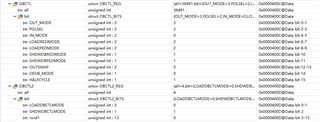
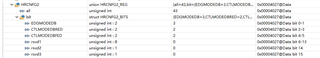
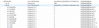
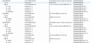
I'd like to use high resolution deadband, but can you share an example of how to config high resolution deadband? 

Regards,

Jack

  • Hello Jack,

    Although there is no high-resolution deadband (HR DB) example projects that I was able to locate, the TRM for your device section 17.15.1.4 discusses the settings available for the HR DB, while section 17.15.1.6 gives a specific written example of how to use those settings appropriately.

    Additionally, the SysConfig tool provides extensive, intuitive manipulation of these values- I recommend using these settings in conjunction with the TRM's examples to learn how the various functions relate to the settings discussed.

    Regards,

    Jason Osborn

  • Hi Jason,

    I'm tring to download SYSCONFIG tools at ti.com, it's good at the begining, but fails after 10%. 

    Back to DEBAND High resolution question, I think I have configured as suggested in TRM, but it still fails to get high resolution on EPWM1B, I can get high resolution on EPWM1A. Here are the register's value, can you please help to analyse the reason why I can't get that?

    1. DBCTL register value 

    2. HRCNFG2 register value

    3. HRCNFG

    4. using UP-DOWN count mode

    5. DBRED DBREDHR DBFED DBFEDHR

  • Hi Jason,

    Can you please share your suggestions according to the registers' value in my previous post? Your support are highly appreciated. 

    Regards,

    Jack

  • Dear c2000 expert,

    May I get further update about this questions? 

    Regards,

    Jack

  • Hello Jack,

    Apologies for the delay in reply! According to this thread, your DBCTL.POLSEL register selection (i.e. inversion of EPWMxB), will result in a non-HR output on EPWMxB. I would suggest setting that value to 0 and seeing about utilizing the HRCNFG.SELOUTB register bit to replicate that behavior in high resolution. Additionally, if you attempt to implement other DB functionality, look through the high resolution control registers before looking through the typical deadband controls- many of the deadband's features are not fully useable in high resolution without further configuration, or are outright replaced.

    Hope that was helpful despite the delay,

    Jason Osborn

  • Hi Jason,

    Thanks for suporting here.

    From TRM, SELOUTB could be inverted the outout EPWMxA signal, although this can realize high resolution on B, but no dead time.

    I have configured the DBCTL.POLSET to 0, and IN_MODE to 0, EPWMxB still do not have high resolution.

    Is it possible to provide example of how to configure PWMxB have high resolution with deadband?

    Regards,

    Jack

  • Hi Jason,

    I have inserted my C code as below to help you reproduce the high resolution problem, can you please help to look at it? Thanks...

    //#############################################################################
    //
    // FILE:   hrpwm_ex4_duty_updown_sfo.c
    //
    // TITLE:  HRPWM Duty Control with UPDOWN Mode.
    //
    //! \addtogroup driver_example_list
    //! <h1>HRPWM Duty Control with UPDOWN Mode</h1>
    //!
    //! This example calls the following TI's MEP Scale Factor Optimizer (SFO)
    //! software library V8 functions:
    //!
    //! \b int \b SFO(); \n
    //! - updates MEP_ScaleFactor dynamically when HRPWM is in use
    //! - updates HRMSTEP register (exists only in EPwm1Regs register space)
    //!   with MEP_ScaleFactor value
    //! - returns 2 if error: MEP_ScaleFactor is greater than maximum value of 255
    //!   (Auto-conversion may not function properly under this condition)
    //! - returns 1 when complete for the specified channel
    //! - returns 0 if not complete for the specified channel
    //!
    //! This example is intended to explain the HRPWM capabilities. The code can be
    //! optimized for code efficiency. Refer to TI's Digital power application
    //! examples and TI Digital Power Supply software libraries for details.
    //!
    //! \b External \b Connections \n
    //!  - Monitor ePWM1/2/3/4 A/B pins on an oscilloscope.
    //
    //#############################################################################
    //
    // $Copyright:
    // Copyright (C) 2022 Texas Instruments Incorporated - http://www.ti.com/
    //
    // Redistribution and use in source and binary forms, with or without 
    // modification, are permitted provided that the following conditions 
    // are met:
    // 
    //   Redistributions of source code must retain the above copyright 
    //   notice, this list of conditions and the following disclaimer.
    // 
    //   Redistributions in binary form must reproduce the above copyright
    //   notice, this list of conditions and the following disclaimer in the 
    //   documentation and/or other materials provided with the   
    //   distribution.
    // 
    //   Neither the name of Texas Instruments Incorporated nor the names of
    //   its contributors may be used to endorse or promote products derived
    //   from this software without specific prior written permission.
    // 
    // THIS SOFTWARE IS PROVIDED BY THE COPYRIGHT HOLDERS AND CONTRIBUTORS 
    // "AS IS" AND ANY EXPRESS OR IMPLIED WARRANTIES, INCLUDING, BUT NOT 
    // LIMITED TO, THE IMPLIED WARRANTIES OF MERCHANTABILITY AND FITNESS FOR
    // A PARTICULAR PURPOSE ARE DISCLAIMED. IN NO EVENT SHALL THE COPYRIGHT 
    // OWNER OR CONTRIBUTORS BE LIABLE FOR ANY DIRECT, INDIRECT, INCIDENTAL, 
    // SPECIAL, EXEMPLARY, OR CONSEQUENTIAL DAMAGES (INCLUDING, BUT NOT 
    // LIMITED TO, PROCUREMENT OF SUBSTITUTE GOODS OR SERVICES; LOSS OF USE,
    // DATA, OR PROFITS; OR BUSINESS INTERRUPTION) HOWEVER CAUSED AND ON ANY
    // THEORY OF LIABILITY, WHETHER IN CONTRACT, STRICT LIABILITY, OR TORT 
    // (INCLUDING NEGLIGENCE OR OTHERWISE) ARISING IN ANY WAY OUT OF THE USE 
    // OF THIS SOFTWARE, EVEN IF ADVISED OF THE POSSIBILITY OF SUCH DAMAGE.
    // $
    //#############################################################################
    //
    // Included Files
    //
    #include "driverlib.h"
    #include "device.h"
    //#include "board.h"
    #include "sfo_v8.h"
    
    /*-----------------------------------------------------------------------------
        Define the structure of the PWM Driver Object
    -----------------------------------------------------------------------------*/
    typedef struct {
            uint16_t PeriodMax;   // Parameter: PWM Half-Period in CPU clock cycles (Q0)
            uint16_t HalfPerMax;  // Parameter: Half of PeriodMax                   (Q0)
            uint16_t Deadband;    // Parameter: PWM deadband in CPU clock cycles    (Q0)
            } PWMGEN ;
    
    #define CHANNEL_B_AS_ZRO_PRD_REF    1
    #define EPWM_TIMER_TBPRD            100UL
    #define MIN_HRPWM_DUTY_PERCENT      4.0/((float32_t)EPWM_TIMER_TBPRD)*100.0
    //
    // Defines
    //
    #define LAST_EPWM_INDEX_FOR_EXAMPLE    5
    #define DEADTIME_ARED (50.752f) /* ns */
    #define DEADTIME_BFED (50.752f) /* ns */
    #define SW_FREQ      (300.0)  /* Khz */
    #define PWM_PERIOD   ((uint32_t)(DEVICE_SYSCLK_FREQ/(SW_FREQ*1000.0)))     //PERIOD
    
    //
    // Globals
    //
    
    float32_t dutyFine = 50.0;
    uint16_t status;
    
    int MEP_ScaleFactor; // Global variable used by the SFO library
                         // Result can be used for all HRPWM channels
                         // This variable is also copied to HRMSTEP
                         // register by SFO() function.
    
    PWMGEN pwm;
    
    volatile uint32_t ePWM[] =
        {EPWM1_BASE, EPWM1_BASE, EPWM2_BASE, EPWM3_BASE, EPWM4_BASE};
    
    //
    // Function Prototypes
    //
    void initHRPWM_ChannelB(uint32_t period);
    void error(void);
    //__interrupt void epwm1ISR(void);
    //__interrupt void epwm2ISR(void);
    //__interrupt void epwm3ISR(void);
    //__interrupt void epwm4ISR(void);
    
    void init_epwm(void);
    //
    // Main
    //
    void main(void)
    {
        uint16_t i = 0;
    
        //
        // Initialize device clock and peripherals
        //
        Device_init();
    
        //
        // Disable pin locks and enable internal pull ups.
        //
        Device_initGPIO();
    
        //
        // Initialize PIE and clear PIE registers. Disables CPU interrupts.
        //
        Interrupt_initModule();
    
        //
        // Initialize the PIE vector table with pointers to the shell Interrupt
        // Service Routines (ISR).
        //
        Interrupt_initVectorTable();
    
        //
        // Assign the interrupt service routines to ePWM interrupts
        //
        //Interrupt_register(INT_EPWM1, &epwm1ISR);
        //Interrupt_register(INT_EPWM2, &epwm2ISR);
        //Interrupt_register(INT_EPWM3, &epwm3ISR);
        //Interrupt_register(INT_EPWM4, &epwm4ISR);
    
        //
        // Calling SFO() updates the HRMSTEP register with calibrated MEP_ScaleFactor.
        // HRMSTEP must be populated with a scale factor value prior to enabling
        // high resolution period control.
        //
        while(status == SFO_INCOMPLETE)
        {
            status = SFO();
            if(status == SFO_ERROR)
            {
                error();   // SFO function returns 2 if an error occurs & # of MEP
            }              // steps/coarse step exceeds maximum of 255.
        }


        //
        // Disable sync(Freeze clock to PWM as well)
        //
        SysCtl_disablePeripheral(SYSCTL_PERIPH_CLK_TBCLKSYNC);
    
        init_epwm();
        //
        // Initialize the EPWM GPIOs and change XBAR inputs from using GPIO0
        //
        //Board_init();
    
        //initHRPWM_ChannelB(EPWM_TIMER_TBPRD);
    
        //
        // Enable sync and clock to PWM
        //
        SysCtl_enablePeripheral(SYSCTL_PERIPH_CLK_TBCLKSYNC);
    
    
        // Enable ePWM interrupts
        //
        //Interrupt_enable(INT_EPWM1);
        //Interrupt_enable(INT_EPWM2);
        //Interrupt_enable(INT_EPWM3);
        //Interrupt_enable(INT_EPWM4);
    
        //
        // Enable Global Interrupt (INTM) and realtime interrupt (DBGM)
        //
        EINT;
        ERTM;
    
    
        for(;;)
        {
             //
             // Sweep DutyFine
             //
             for(dutyFine = MIN_HRPWM_DUTY_PERCENT; dutyFine < (100.0-MIN_HRPWM_DUTY_PERCENT); dutyFine += 0.0001)
             {
                 DEVICE_DELAY_US(100);
                 for(i=1; i<LAST_EPWM_INDEX_FOR_EXAMPLE; i++)
                 {
                     float32_t count = ((100.0 - dutyFine) * (float32_t)(pwm.HalfPerMax << 8))/100.0;
                     uint32_t compCount = (count);
                     uint32_t hrCompCount = (compCount & (0x000000FF));
                     if (hrCompCount == 0)
                     {
                         //
                         // Add 1 to not have CMPxHR = 0
                         //
                         compCount |= 0x00000001;
                     }
                     HRPWM_setCounterCompareValue(EPWM1_BASE, HRPWM_COUNTER_COMPARE_A, compCount);
    #if CHANNEL_B_AS_ZRO_PRD_REF == 0
                     HRPWM_setCounterCompareValue(EPWM1_BASE, HRPWM_COUNTER_COMPARE_B, compCount);
    #endif
                 }
    
                 //
                 // Call the scale factor optimizer lib function SFO()
                 // periodically to track for any change due to temp/voltage.
                 // This function generates MEP_ScaleFactor by running the
                 // MEP calibration module in the HRPWM logic. This scale
                 // factor can be used for all HRPWM channels. The SFO()
                 // function also updates the HRMSTEP register with the
                 // scale factor value.
                 //
                 status = SFO(); // in background, MEP calibration module
                                 // continuously updates MEP_ScaleFactor
    
                 if (status == SFO_ERROR)
                 {
                     error();   // SFO function returns 2 if an error occurs & #
                                // of MEP steps/coarse step
                 }              // exceeds maximum of 255.
             }
         }
    }
    
    void init_epwm(void)
    {
        pwm.PeriodMax = PWM_PERIOD;
        pwm.HalfPerMax=pwm.PeriodMax>>1;
        pwm.Deadband  = 0;
    
        /************************* EPWM1 CONFIGURATION ************************/
        /* 0. force EPWM1A and EPWM1B continuous low */
        EPWM_setActionQualifierContSWForceAction(EPWM1_BASE, EPWM_AQ_OUTPUT_A, EPWM_AQ_SW_OUTPUT_LOW);
        EPWM_setActionQualifierContSWForceAction(EPWM1_BASE, EPWM_AQ_OUTPUT_B, EPWM_AQ_SW_OUTPUT_LOW);
        EPWM_setActionQualifierContSWForceShadowMode(EPWM1_BASE, EPWM_AQ_SW_SH_LOAD_ON_CNTR_PERIOD);
        EPWM_setActionQualifierShadowLoadMode(EPWM1_BASE, EPWM_ACTION_QUALIFIER_A, EPWM_AQ_LOAD_ON_CNTR_PERIOD);
        EPWM_setActionQualifierShadowLoadMode(EPWM1_BASE, EPWM_ACTION_QUALIFIER_B, EPWM_AQ_LOAD_ON_CNTR_PERIOD);
        EPWM_setDeadBandControlShadowLoadMode(EPWM1_BASE, EPWM_DB_LOAD_ON_CNTR_PERIOD);
        EPWM_setRisingEdgeDelayCountShadowLoadMode(EPWM1_BASE, EPWM_RED_LOAD_ON_CNTR_PERIOD);
        EPWM_setFallingEdgeDelayCountShadowLoadMode(EPWM1_BASE, EPWM_FED_LOAD_ON_CNTR_PERIOD);
    #ifdef GLDEN
        EPWM_enableGlobalLoad(EPWM1_BASE);
        EPWM_setGlobalLoadTrigger(EPWM1_BASE, EPWM_GL_LOAD_PULSE_CNTR_PERIOD);
        EPWM_setGlobalLoadEventPrescale(EPWM1_BASE, 1);
        EPWM_enableGlobalLoadRegisters(EPWM1_BASE, 0xFFFF);
    #endif
        /* 1. Set-up TBCLK */
        EPWM_setTimeBasePeriod(EPWM1_BASE, pwm.HalfPerMax);
        EPWM_setPhaseShift(EPWM1_BASE, 0U);
        EPWM_disablePhaseShiftLoad(EPWM1_BASE);
        EPWM_setTimeBaseCounter(EPWM1_BASE, 0U);
        EPWM_enableSyncOutPulseSource(EPWM1_BASE, EPWM_SYNC_OUT_PULSE_ON_CNTR_ZERO);
    
        /* 2. Set Compare values */
        EPWM_setCounterCompareValue(EPWM1_BASE,
                                    EPWM_COUNTER_COMPARE_A,
                                    2);
        EPWM_setCounterCompareValue(EPWM1_BASE,
                                    EPWM_COUNTER_COMPARE_B,
                                    0);
        EPWM_setCounterCompareValue(EPWM1_BASE,
                                    EPWM_COUNTER_COMPARE_C,
                                    pwm.HalfPerMax);
        EPWM_setCounterCompareValue(EPWM1_BASE,
                                    EPWM_COUNTER_COMPARE_D,
                                    (pwm.HalfPerMax - 30));
    
        /* 3. Set up counter mode */
        EPWM_setTimeBaseCounterMode(EPWM1_BASE, EPWM_COUNTER_MODE_UP_DOWN);
        EPWM_setClockPrescaler(EPWM1_BASE,
                               EPWM_CLOCK_DIVIDER_1,
                               EPWM_HSCLOCK_DIVIDER_1);
    
        /* 4. Set up shadowing */
        EPWM_setCounterCompareShadowLoadMode(EPWM1_BASE,
                                             EPWM_COUNTER_COMPARE_A,
                                             EPWM_COMP_LOAD_ON_CNTR_ZERO_PERIOD);
        EPWM_setCounterCompareShadowLoadMode(EPWM1_BASE,
                                             EPWM_COUNTER_COMPARE_B,
                                             EPWM_COMP_LOAD_ON_CNTR_ZERO_PERIOD);
    
        /* 5. Set actions */
        EPWM_setActionQualifierAction(EPWM1_BASE,
                                      EPWM_AQ_OUTPUT_A,
                                      EPWM_AQ_OUTPUT_HIGH,
                                      EPWM_AQ_OUTPUT_ON_TIMEBASE_UP_CMPA);
        EPWM_setActionQualifierAction(EPWM1_BASE,
                                      EPWM_AQ_OUTPUT_A,
                                      EPWM_AQ_OUTPUT_LOW,
                                      EPWM_AQ_OUTPUT_ON_TIMEBASE_DOWN_CMPA);
    
        EPWM_setActionQualifierAction(EPWM1_BASE,
                                      EPWM_AQ_OUTPUT_B,
                                      EPWM_AQ_OUTPUT_HIGH,
                                      EPWM_AQ_OUTPUT_ON_TIMEBASE_UP_CMPA);
        EPWM_setActionQualifierAction(EPWM1_BASE,
                                      EPWM_AQ_OUTPUT_B,
                                      EPWM_AQ_OUTPUT_LOW,
                                      EPWM_AQ_OUTPUT_ON_TIMEBASE_DOWN_CMPA);
    
        /* 6. DBCTL */
        EPWM_setDeadBandDelayMode(EPWM1_BASE,EPWM_DB_RED,true);
        EPWM_setDeadBandDelayMode(EPWM1_BASE,EPWM_DB_FED,true);
    
        EPWM_setDeadBandDelayPolarity(EPWM1_BASE,EPWM_DB_RED,EPWM_DB_POLARITY_ACTIVE_HIGH);
        EPWM_setDeadBandDelayPolarity(EPWM1_BASE,EPWM_DB_FED,EPWM_DB_POLARITY_ACTIVE_HIGH);
    
        EPWM_setRisingEdgeDeadBandDelayInput(EPWM1_BASE, EPWM_DB_INPUT_EPWMA);
        EPWM_setFallingEdgeDeadBandDelayInput(EPWM1_BASE, EPWM_DB_INPUT_EPWMA);
    
        EPWM_setDeadBandControlShadowLoadMode(EPWM1_BASE,EPWM_DB_LOAD_ON_CNTR_ZERO_PERIOD);
    
        EPWM_setRisingEdgeDelayCountShadowLoadMode(EPWM1_BASE,EPWM_RED_LOAD_ON_CNTR_ZERO_PERIOD);
        EPWM_setFallingEdgeDelayCountShadowLoadMode(EPWM1_BASE,EPWM_FED_LOAD_ON_CNTR_ZERO_PERIOD);
    
        EPWM_setDeadBandCounterClock(EPWM1_BASE,EPWM_DB_COUNTER_CLOCK_HALF_CYCLE);
    
        //HWREGH(EPWM1_BASE + EPWM_O_DBCTL) = BUCKON_DBCTL;
        //HWREGH(EPWM1_BASE + EPWM_O_DBCTL2) = BUCK_DBCTL2;
        //EPWM_setActionQualifierContSWForceAction(EPWM1_BASE, EPWM_AQ_OUTPUT_B, EPWM_AQ_SW_OUTPUT_HIGH);
        /* 7. RED and FED config */
    
        /* Half cycle enable delay count calculation */
        {
            float32_t dbred_time = DEADTIME_ARED;
            float32_t dbfed_time = DEADTIME_BFED;
    
            float32_t tbclkPeriod = (1e9/DEVICE_SYSCLK_FREQ);
    
            uint32_t dbred_count = (dbred_time * 2.0f) / tbclkPeriod;
            uint32_t dbfed_count = (dbfed_time * 2.0f) / tbclkPeriod;
    
            EPWM_setRisingEdgeDelayCount(EPWM1_BASE, dbred_count);
            EPWM_setFallingEdgeDelayCount(EPWM1_BASE,dbfed_count);
            //HWREG(EPWM1_BASE + EPWM_O_DBRED) = dbred_count;
            //HWREG(EPWM1_BASE + EPWM_O_DBFED) = dbfed_count;
        }
    
    
        HRPWM_setMEPEdgeSelect(EPWM1_BASE, HRPWM_CHANNEL_A, HRPWM_MEP_CTRL_RISING_AND_FALLING_EDGE);
        HRPWM_setMEPControlMode(EPWM1_BASE, HRPWM_CHANNEL_A, HRPWM_MEP_DUTY_PERIOD_CTRL);
    
        /*
         * Set up shadowing
         * MUST BE CTR=(ZER & PRD)
         */
        HRPWM_setCounterCompareShadowLoadEvent(EPWM1_BASE, HRPWM_CHANNEL_A, HRPWM_LOAD_ON_CNTR_ZERO_PERIOD);
    
        HRPWM_setMEPEdgeSelect(EPWM1_BASE, HRPWM_CHANNEL_B, HRPWM_MEP_CTRL_RISING_AND_FALLING_EDGE);
        HRPWM_setMEPControlMode(EPWM1_BASE, HRPWM_CHANNEL_B, HRPWM_MEP_DUTY_PERIOD_CTRL);
    
        /*
         * Set up shadowing
         * MUST BE CTR=(ZER & PRD)
         */
        HRPWM_setCounterCompareShadowLoadEvent(EPWM1_BASE, HRPWM_CHANNEL_B, HRPWM_LOAD_ON_CNTR_ZERO_PERIOD);
    
        HRPWM_setDeadbandMEPEdgeSelect(EPWM1_BASE, HRPWM_DB_MEP_CTRL_RED_FED);
        HRPWM_setRisingEdgeDelayLoadMode(EPWM1_BASE, HRPWM_LOAD_ON_CNTR_ZERO_PERIOD);
        HRPWM_setFallingEdgeDelayLoadMode(EPWM1_BASE, HRPWM_LOAD_ON_CNTR_ZERO_PERIOD);
    
        HRPWM_enableAutoConversion(EPWM1_BASE);
    
        HRPWM_enablePeriodControl(EPWM1_BASE);
    
        HRPWM_enablePhaseShiftLoad(EPWM1_BASE);
    
        EPWM_setActionQualifierContSWForceAction(EPWM1_BASE, EPWM_AQ_OUTPUT_A, EPWM_AQ_SW_DISABLED);
        EPWM_setActionQualifierContSWForceAction(EPWM1_BASE, EPWM_AQ_OUTPUT_B, EPWM_AQ_SW_DISABLED);
    
        GPIO_setPinConfig(GPIO_0_EPWM1_A);
        GPIO_setPinConfig(GPIO_1_EPWM1_B);
    }
    
    //
    // error - Halt debugger when called
    //
    void error (void)
    {
        ESTOP0;         // Stop here and handle error
    }
    

  • Hello Jack,

    When it comes to using HRPWM, the Driverlib examples for your device are fantastic resources- and several of them utilize HRPWM channel B. That said, I would like to ask what, exactly, you're referring to when you state that EPWMxB does not have high resolution? Are you stating that EPWMxA has RED high resolution behavior, while EPWMxB has no high resolution behavior?

    Regards,

    Jason Osborn

  • Hi Jason,

    Yes, EPWMxA has RED high resolution, but EPWMxB do not have high resolution in the above source code configuration.

    Regards,

    Jack

  • Hello Jack,

    A clarifying question. Your code is currently set up such that the final output of ePWMxB is being generated via an FED-adjusted ePWMxA, instead of the AQ's ePWMxB output (i.e. nothing the AQ does to ePWMxB has any effect on the final output) according to

    EPWM_setFallingEdgeDeadBandDelayInput(EPWM1_BASE, EPWM_DB_INPUT_EPWMA);

    Is this correct? This should mean that the ePWMxB is identical to ePWMxA, but with FED instead of RED. If this is not what you see, could you provide the waveforms you're seeing on your GPIO pins?

    Regards,
    Jason Osborn

  • Hi Jason,

    Thanks for your effort here, and sorry for my delay reponse.

    Actually, what I want is that EPWM1B is complementary with EPWM1A and have some deadtime, but I can't get high resolution on EPWM1B.

    So in my testing code, in order to find out what makes EPWM1B have no high resolution. I configured both FE and RE's input using the same source( EPWMA), and just have different FED and RED. Hence, your you understanding is correct. ("This should mean that the ePWMxB is identical to ePWMxA, but with FED instead of RED.")

    In my testing code, the duty cycle is increase and decrease with very slow speed. In the waveform, I can see EPWM1A increase/decrease with fine step, but there is coarse step(10ns step) increase/decrease on EPWM1B. This can be easily test with my code.

    Here I need you and your team support to find out how to configure EPWM1B to have high resolution with using dead band. If I have something missing in my testing code, please correct it. Thanks...

    Regards,

    Jack

  • Jack,

    Well. I realized while taking a look at it while testing that we both seem to have overlooked something... a bit important.

    Line 80

    #define CHANNEL_B_AS_ZRO_PRD_REF    1

    Please change this to

    #define CHANNEL_B_AS_ZRO_PRD_REF    0

    Regards,

    Jason Osborn

    (Just accuracy's sake, I went back and checked to see if altering the value of POLSEL affected the functionality of HRPWM. As far as I can tell, POLSEL doesn't have any effect on HRPWM in this version of type-4 HRPWM.)

  • Hi Jason,

    I can see high resolution on EPWM1B after changing #define CHANNEL_B_AS_ZRO_PRD_REF    0. 

    However, I have looked through with my code, and find that this macro is used in updating CMPB register value only, but I did't use CMPB in ACTION QUALIFICATION configuration, can you please help me know why CMPB has to be updated in high resolution? 

    Here is the only case that use CHANNEL_B_AS_ZRO_PRD_REF.

    HRPWM_setCounterCompareValue(EPWM1_BASE, HRPWM_COUNTER_COMPARE_A, compCount);
    #if CHANNEL_B_AS_ZRO_PRD_REF == 0
    HRPWM_setCounterCompareValue(EPWM1_BASE, HRPWM_COUNTER_COMPARE_B, compCount);
    #endif

  • Hello Jack,

    As described in section 17.15.1 of the device's TRM, CMPxHR is technically unrelated to CMPx, and the HRPWM_setCounterCompareValue() func sets both. The former is used to generate/control most of the high-resolution behavior of ePWMx. (If you're wondering why the CMPB value is relevant at all, the answer is lines 376 & 377!)

    Regards,

    Jason Osborn