This thread has been locked.

If you have a related question, please click the "Ask a related question" button in the top right corner. The newly created question will be automatically linked to this question.

TMS320F28379D: What are the possible causes for very poor drive strength on TMS320F28379D JTAG TDO ?

Part Number: TMS320F28379D

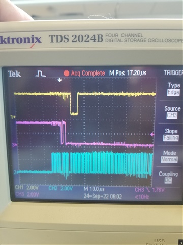
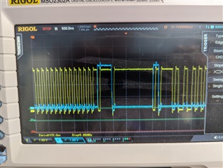
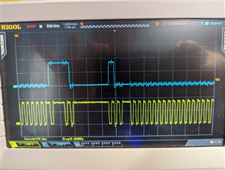
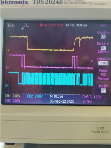
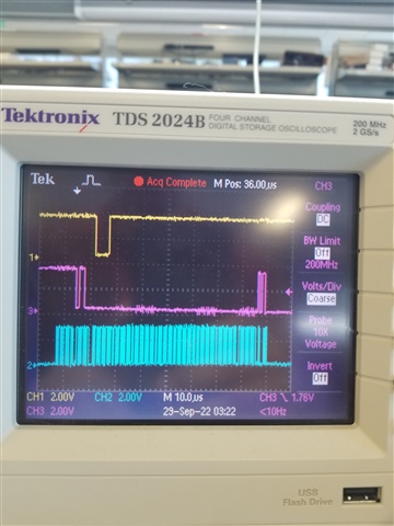
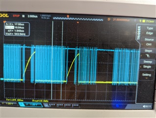
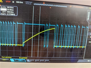
JTAG CLK - Blue Trace

JTAG TDO from DSP - Yellow.

I checked the 3V3 IO Rail and it is solid (no dips during transitions and is 3.29V).
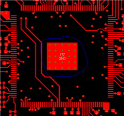
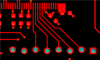
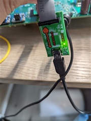
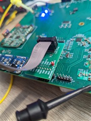
176-LQFP Package

It is possible that the assembly house did not solder the EP gnd pad properly.  Does this look like the case here ?
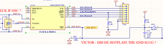
TRST is HIGH btw

  • Hi Michael, 

    I'm having our JTAG expert look at this but they are currently out of office. Please expect a reply tomorrow

    Regards,

    Peter

  • Hi Michael,

    I am curious to know more about your setup. What do you mean by your "EP gnd pad"? Are you having this problem with multiple devices or just a single f28379d? Also, how long are the traces between the JTAG header and the MCU and where are you physically placing the probes on the traces to see these signals? Also, could you scope your other signals? Lastly, I don't think it is the cause of this issue, but what JTAG emulator are you using to connect to the device? 

    Best Regards,

    Ben Collier

  • The package of the device uses an ground pad connection: see picture

    There is only one device on the JTAG chain and the traces are about 0.5".  

    Signals coming from the XDS110 are fine but the culprit for the malfunctioning JTAG is the TDO being driven by the F28379D.

    Scope probes were on the JTAG header.

    Jtag Emulator: XDS110

  • Hi again Michael,

    I have just tested the JTAG connection of the device without the ground pad connected. While it does make a difference in TDO signal quality, it does not seem like it is causing the problem. TDO is still driven acceptably as seen in the attached oscilloscope graphic where TDO is yellow, TMS is purple, and TCK is blue.

    Is it possible that the individual F28379D device you are using is damaged? Would it be possible for you to try your setup with a different F28379D device? Also, would you be able to provide your scoped signals again like the above graphic and include TMS? This way we could possibly see if something unexpected is happening with the TAP state machine. 

    Best Regards,

    Ben Collier

  • Hi,

    Still setting up my Logic Analyzer so I can capture more than 2 signals

    I also setup my FT232H to try and do JTAG but got this error:

    C28xx_CPU1: Trouble Writing Memory Block at 0x5f412 on Page 1 of Length 0x1: Read timed out
    C28xx_CPU1: GEL: Error while executing OnTargetConnect(): Target failed to write 0x0005F412@Data
    at *((int*) 0x5F412)=0x000F [f28379d_cpu1.gel:79]
    at OnTargetConnect()
    C28xx_CPU2: Trouble Writing Memory Block at 0x5f412 on Page 1 of Length 0x1: Read timed out
    C28xx_CPU2: GEL: Error while executing OnTargetConnect(): Target failed to write 0x0005F412@Data
    at *((int*) 0x5F412)=0x000F [f28379d_cpu2.gel:75]
    at OnTargetConnect()
    C28xx_CPU1: Failed CPU Reset: Unsupported GTI Function.
    C28xx_CPU1: Trouble Writing Memory Block at 0x5d122 on Page 1 of Length 0x2: Read timed out
    C28xx_CPU1: GEL: Error while executing OnReset(-1): Target failed to write 0x0005D122@Data
    at *((long int*) 0x5D122)=0xA5A50000 [f28379d_cpu1.gel:28]
    at OnReset(-(1))
    C28xx_CPU1: GEL: Error calling OnPreFileLoaded(): Reset failed: retcode=-1
    C28xx_CPU1: Trouble Writing Memory Block at 0x0 on Page 0 of Length 0x2: Read timed out
    C28xx_CPU1: File Loader: Verification failed: Target failed to write 0x000000@Program
    C28xx_CPU1: GEL: File: D:\Development\TI\Workbench\gpio_ex2_toggle\CPU1_RAM\gpio_ex2_toggle.out: Load failed.

    Finally here is a screen shot of TCK and TMS

    BTW Yes the part could be damaged due to a poor assembly house.  Our next move is to fabricate a REV B of this PCB that uses the traditional 20 pin JTAG header for the XDS110 Probe

  • Hi, 

    That sounds like a good next move. It also does look like something odd might be going on with the TAP state machine. Could you set your oscilloscope to take a single sample, and to trigger it on the falling edge of TMS? Then use the 'test connection' option in the target configuration menu on CCS? That should produce a plot like the one I shared, showing the same patterns on TMS and TCK. Also, could you share the output log from testing connection?

    Best Regards,

    Ben Collier

  • TMS triggered on falling edge, looks like your picture

    OUTPUT LOG FROM TESTING CONNECTION

    [Start]

    Execute the command:

    %ccs_base%/common/uscif/dbgjtag -f %boarddatafile% -rv -o -S integrity

    [Result]


    -----[Print the board config pathname(s)]------------------------------------

    C:\Users\MICHAE~1\AppData\Local\TEXASI~1\
    CCS\CCS1200\0\0\BrdDat\testBoard.dat

    -----[Print the reset-command software log-file]-----------------------------

    This utility has selected a 100/110/510 class product.
    This utility will load the adapter 'jioxds110.dll'.
    The library build date was 'Jun 17 2022'.
    The library build time was '22:30:41'.
    The library package version is '9.8.0.00235'.
    The library component version is '35.35.0.0'.
    The controller does not use a programmable FPGA.
    The controller has a version number of '5' (0x00000005).
    The controller has an insertion length of '0' (0x00000000).
    This utility will attempt to reset the controller.
    This utility has successfully reset the controller.

    -----[Print the reset-command hardware log-file]-----------------------------

    The scan-path will be reset by toggling the JTAG TRST signal.
    The controller is the XDS110 with USB interface.
    The link from controller to target is direct (without cable).
    The software is configured for XDS110 features.
    The controller cannot monitor the value on the EMU[0] pin.
    The controller cannot monitor the value on the EMU[1] pin.
    The controller cannot control the timing on output pins.
    The controller cannot control the timing on input pins.
    The scan-path link-delay has been set to exactly '0' (0x0000).

    -----[An error has occurred and this utility has aborted]--------------------

    This error is generated by TI's USCIF driver or utilities.

    The value is '-233' (0xffffff17).
    The title is 'SC_ERR_PATH_BROKEN'.

    The explanation is:
    The JTAG IR and DR scan-paths cannot circulate bits, they may be broken.
    An attempt to scan the JTAG scan-path has failed.
    The target's JTAG scan-path appears to be broken
    with a stuck-at-ones or stuck-at-zero fault.

    [End]

  • Hi again Michael,

    It was looking to me like TMS was not functioning exactly as expected in the scope images you sent, so I decided to try connecting with the XDS110 and I have replicated your issue with the poor driving strength and the broken connection. My XDS100 connects fine to the same setup, so it seems the XDS110 is the source of the problem. I am not yet sure how the specific JTAG debugger is affecting the TDO signal in this way, but I plan to meet with someone from our JTAG debugger team tomorrow to discuss. While we are trying to find a more permanent solution, do you have an XDS100 or XDS200 you would be able to try with your setup? 

    Best Regards,

    Ben Collier

  • Hi Mike,

    I have been using the Olimex XDS100V2, if you would like to try that in the meantime. Our team will still try to find the root of the problem with the XDS110. Also, due to E2E website maintenance, I will not be able to get back to you again until Monday, and this page may be inaccessible for a few days.   

    Best Regards,

    Ben Collier

  • Ben You Da Man !

    OK I will order the Olimex XDS100V2 and wait to see what you have to say about the XDS110 (which should be compatible with the C2000 family of DSPs ?!?)

    THANK YOU !!!!

  • Hey Ben,

    Unfortunately this did not work

    [Start]

    Execute the command:

    %ccs_base%/common/uscif/dbgjtag -f %boarddatafile% -rv -o -F inform,logfile=yes -S pathlength -S integrity

    [Result]


    -----[Print the board config pathname(s)]------------------------------------

    C:\Users\MICHAE~1\AppData\Local\TEXASI~1\
    CCS\CCS1200\0\0\BrdDat\testBoard.dat

    -----[Print the reset-command software log-file]-----------------------------

    This utility has selected a 100/110/510 class product.
    This utility will load the adapter 'jioserdesusb.dll'.
    The library build date was 'Jun 17 2022'.
    The library build time was '22:30:41'.
    The library package version is '9.8.0.00235'.
    The library component version is '35.35.0.0'.
    The controller does not use a programmable FPGA.
    The controller has a version number of '4' (0x00000004).
    The controller has an insertion length of '0' (0x00000000).
    This utility will attempt to reset the controller.
    This utility has successfully reset the controller.

    -----[Print the reset-command hardware log-file]-----------------------------

    The scan-path will be reset by toggling the JTAG TRST signal.
    The controller is the FTDI FT2232 with USB interface.
    The link from controller to target is direct (without cable).
    The software is configured for FTDI FT2232 features.
    The controller cannot monitor the value on the EMU[0] pin.
    The controller cannot monitor the value on the EMU[1] pin.
    The controller cannot control the timing on output pins.
    The controller cannot control the timing on input pins.
    The scan-path link-delay has been set to exactly '0' (0x0000).

    -----[The log-file for the JTAG TCLK output generated from the PLL]----------

    There is no hardware for programming the JTAG TCLK frequency.

    -----[Measure the source and frequency of the final JTAG TCLKR input]--------

    There is no hardware for measuring the JTAG TCLK frequency.

    -----[Perform the standard path-length test on the JTAG IR and DR]-----------

    This path-length test uses blocks of 64 32-bit words.

    The test for the JTAG IR instruction path-length failed.
    The JTAG IR instruction scan-path is stuck-at-ones.

    The test for the JTAG DR bypass path-length failed.
    The JTAG DR bypass scan-path is stuck-at-ones.

    -----[Perform the Integrity scan-test on the JTAG IR]------------------------

    This test will use blocks of 64 32-bit words.
    This test will be applied just once.

    Do a test using 0xFFFFFFFF.
    Test 1 Word 0: scanned out 0xFFFFFFFF and scanned in 0xFFFFFFC1.
    Scan tests: 1, skipped: 0, failed: 1
    Do a test using 0x00000000.
    Test 2 Word 0: scanned out 0x00000000 and scanned in 0x0000003F.
    Scan tests: 2, skipped: 0, failed: 2
    Do a test using 0xFE03E0E2.
    Test 3 Word 0: scanned out 0xFE03E0E2 and scanned in 0xFFFFFFFF.
    Test 3 Word 1: scanned out 0xFE03E0E2 and scanned in 0xFFFFFFFF.
    Test 3 Word 2: scanned out 0xFE03E0E2 and scanned in 0xFFFFFFFF.
    Test 3 Word 3: scanned out 0xFE03E0E2 and scanned in 0xFFFFFFFF.
    Test 3 Word 4: scanned out 0xFE03E0E2 and scanned in 0xFFFFFFFF.
    Test 3 Word 5: scanned out 0xFE03E0E2 and scanned in 0xFFFFFFFF.
    The details of the first 8 errors have been provided.
    The utility will now report only the count of failed tests.
    Scan tests: 3, skipped: 0, failed: 3
    Do a test using 0x01FC1F1D.
    Scan tests: 4, skipped: 0, failed: 4
    Do a test using 0x5533CCAA.
    Scan tests: 5, skipped: 0, failed: 5
    Do a test using 0xAACC3355.
    Scan tests: 6, skipped: 0, failed: 6
    Some of the values were corrupted - 67.2 percent.

    The JTAG IR Integrity scan-test has failed.

    -----[Perform the Integrity scan-test on the JTAG DR]------------------------

    This test will use blocks of 64 32-bit words.
    This test will be applied just once.

    Do a test using 0xFFFFFFFF.
    Test 1 Word 0: scanned out 0xFFFFFFFF and scanned in 0xFFFFC02F.
    Scan tests: 1, skipped: 0, failed: 1
    Do a test using 0x00000000.
    Test 2 Word 0: scanned out 0x00000000 and scanned in 0xFFFFFFFF.
    Test 2 Word 1: scanned out 0x00000000 and scanned in 0xFFFFFFFF.
    Test 2 Word 2: scanned out 0x00000000 and scanned in 0xFFFFFFFF.
    Test 2 Word 3: scanned out 0x00000000 and scanned in 0xFFFFFFFF.
    Test 2 Word 4: scanned out 0x00000000 and scanned in 0xFFFFFFFF.
    Test 2 Word 5: scanned out 0x00000000 and scanned in 0xFFFFFFFF.
    Test 2 Word 6: scanned out 0x00000000 and scanned in 0xFFFFFFFF.
    The details of the first 8 errors have been provided.
    The utility will now report only the count of failed tests.
    Scan tests: 2, skipped: 0, failed: 2
    Do a test using 0xFE03E0E2.
    Scan tests: 3, skipped: 0, failed: 3
    Do a test using 0x01FC1F1D.
    Scan tests: 4, skipped: 0, failed: 4
    Do a test using 0x5533CCAA.
    Scan tests: 5, skipped: 0, failed: 5
    Do a test using 0xAACC3355.
    Scan tests: 6, skipped: 0, failed: 6
    Some of the values were corrupted - 83.6 percent.

    The JTAG DR Integrity scan-test has failed.

    [End]

  • Hi Michael,

    I am sorry that the XDS100V2 did not work for you. Could you please provide images of the JTAG signals (TCK and TMS) on your oscilloscope again? If possible, trigger a single capture on the falling edge of TMS again. Also, it would helpful to see TDO as well if that is possible. 

    Just for reference, here are my scope signals when using the XDS110 (TDO is yellow, TMS is purple, TCK is blue)


    Here are my signals with the Olimex XDS100V2 (TDO is yellow, TMS is purple, TCK is blue)

    It would be helpful to see if you experience the same differences in signal shape when you switch between XDS110 and XDS100V2.

    Best Regards,

    Ben Collier

  • Hey Ben,

    Great news.  I got it to scan the JTAG properly.  The problem is that I "think" the JTAG chain operates at about 10MHz.

    The signal integrity with my flying lead setup was/is pretty poor.  So while you and I were doing the debug steps I 

    fabbed a cheap adapter (files attached for other people) and VOILA it programmed.  Attached are some pictures 

    of the setup.  I am sure other people have been bitten by this.  Thank you for all your help and if you want I will 

    build you an adapter and send it to you free of charge (:-)  Just private message me.

     JTAG C20 Adapter.zip

    [Start]

    Execute the command:

    %ccs_base%/common/uscif/dbgjtag -f %boarddatafile% -rv -o -F inform,logfile=yes -S pathlength -S integrity

    [Result]


    -----[Print the board config pathname(s)]------------------------------------

    C:\Users\MICHAE~1\AppData\Local\TEXASI~1\
    CCS\CCS1200\0\0\BrdDat\testBoard.dat

    -----[Print the reset-command software log-file]-----------------------------

    This utility has selected a 100/110/510 class product.
    This utility will load the adapter 'jioserdesusb.dll'.
    The library build date was 'Jun 17 2022'.
    The library build time was '22:30:41'.
    The library package version is '9.8.0.00235'.
    The library component version is '35.35.0.0'.
    The controller does not use a programmable FPGA.
    The controller has a version number of '4' (0x00000004).
    The controller has an insertion length of '0' (0x00000000).
    This utility will attempt to reset the controller.
    This utility has successfully reset the controller.

    -----[Print the reset-command hardware log-file]-----------------------------

    The scan-path will be reset by toggling the JTAG TRST signal.
    The controller is the FTDI FT2232 with USB interface.
    The link from controller to target is direct (without cable).
    The software is configured for FTDI FT2232 features.
    The controller cannot monitor the value on the EMU[0] pin.
    The controller cannot monitor the value on the EMU[1] pin.
    The controller cannot control the timing on output pins.
    The controller cannot control the timing on input pins.
    The scan-path link-delay has been set to exactly '0' (0x0000).

    -----[The log-file for the JTAG TCLK output generated from the PLL]----------

    There is no hardware for programming the JTAG TCLK frequency.

    -----[Measure the source and frequency of the final JTAG TCLKR input]--------

    There is no hardware for measuring the JTAG TCLK frequency.

    -----[Perform the standard path-length test on the JTAG IR and DR]-----------

    This path-length test uses blocks of 64 32-bit words.

    The test for the JTAG IR instruction path-length succeeded.
    The JTAG IR instruction path-length is 6 bits.

    The test for the JTAG DR bypass path-length succeeded.
    The JTAG DR bypass path-length is 1 bits.

    -----[Perform the Integrity scan-test on the JTAG IR]------------------------

    This test will use blocks of 64 32-bit words.
    This test will be applied just once.

    Do a test using 0xFFFFFFFF.
    Scan tests: 1, skipped: 0, failed: 0
    Do a test using 0x00000000.
    Scan tests: 2, skipped: 0, failed: 0
    Do a test using 0xFE03E0E2.
    Scan tests: 3, skipped: 0, failed: 0
    Do a test using 0x01FC1F1D.
    Scan tests: 4, skipped: 0, failed: 0
    Do a test using 0x5533CCAA.
    Scan tests: 5, skipped: 0, failed: 0
    Do a test using 0xAACC3355.
    Scan tests: 6, skipped: 0, failed: 0
    All of the values were scanned correctly.

    The JTAG IR Integrity scan-test has succeeded.

    -----[Perform the Integrity scan-test on the JTAG DR]------------------------

    This test will use blocks of 64 32-bit words.
    This test will be applied just once.

    Do a test using 0xFFFFFFFF.
    Scan tests: 1, skipped: 0, failed: 0
    Do a test using 0x00000000.
    Scan tests: 2, skipped: 0, failed: 0
    Do a test using 0xFE03E0E2.
    Scan tests: 3, skipped: 0, failed: 0
    Do a test using 0x01FC1F1D.
    Scan tests: 4, skipped: 0, failed: 0
    Do a test using 0x5533CCAA.
    Scan tests: 5, skipped: 0, failed: 0
    Do a test using 0xAACC3355.
    Scan tests: 6, skipped: 0, failed: 0
    All of the values were scanned correctly.

    The JTAG DR Integrity scan-test has succeeded.

    [End]

  • Hi again Michael,

    That is great news, I am glad to hear that you were able to connect with the XDS100V2 and your adapter! While I appreciate the offer to send me an adapter, I don't think that would be necessary, as I see you have already uploaded the schematic. Also, as you mentioned earlier, the XDS110 should be compatible with all C2000 devices, so I will still update this thread again when I figure out what was going on with the XDS110. 

    Best Regards,

    Ben Collier

  • Hey Ben, I included the design files for the adapter in the ZIP file in the above post.

    The XDS110 WORKED with the adapter.  I think signal integrity was the key issue here.

    Mike

  • Hi again Mike,

    That is great to hear! I just found that my issue with the XDS110 was actually caused by a broken part, so it makes sense that your XDS110 is actually able to connect. I am sorry that you bought the XDS100V2 when it wasn't necessary, but I am glad to hear that you are up and running!

    Best Regards,

    Ben Collier

  • The thing is working, so I have an extra XDS100V2 ... not crying over it :-)

    Ben - The whole team here really appreciates your excellent support !