Other Parts Discussed in Thread: SFRA
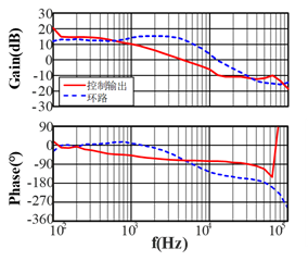
When measuring the bode diagram of the loop characteristics with FRA(The model is Venable 7405), it is found that the zero frequency poles of the digital PI compensator do not seem to be able to compensate. The gain in the low frequency band is very low, and the phase does not drop by 90 degrees, which is completely different from the pole compensation. However, the high frequency band is similar to the simulation results. The results of multiple measurements are the same. Have you encountered similar problems?
In the figure below, the blue color is the FRA experiment result of the loop transfer function, and the red color is the power level experiment result. In the simulation, the ideal situation is that the low frequency gain decreases at a slope of - 20dB, rather than the very gentle one I measured. The power level result is similar to the theoretical simulation.
In order to compare with the experiment, I changed the pole position in the simulation(in SIMPLIS) from 0Hz to 2kHz, and obtained the following results:
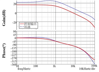
It can be seen that this result is close to the experimental measurement, so I suspect that the pole position has moved, but no similar situation is found.
I wonder if the pole of PI compensator may move?