Other Parts Discussed in Thread: C2000WARE, MOTORWARE
In another thread attempting to get sci to work with motorware drivers, I had a lot of responses and in the end Ms. Marlyn Rosales Castaneda suggested that I simplify the problem and just try to write a simple program with only the SCI code and no motor code to pinpoint where the problem is in my program. I have done that, but unfortunately still having issues and I am not quite sure where. I have had success getting data to show up with my salae logic analyzer and running the sci_echoback program that is located in the ti folder system at ti/C2000/C2000Ware_4_01_00_00/device_support/f2806x/c28/sci_echoback. I created a brand new program and imported the folders, such as the SCI.h/SCI.c, GPIO.h/...... etc, that proj_lab10d used, located in, ti/C2000/C2000Ware_4_01_00_00/sw/solutions/instaspin_foc/boards/boostxldrv8301_revB/f28x/f2806xF/projects/ccs. In my simple program I followed the ti/motorware/motorware_1_01_00_18/docs/tutorials/motorware_hal_tutorial.pdf, that guides the user to adding sci functionality into a Motorware project. However, I was unable to see any data coming through my salae logic analyzer. I looked at all the registers in both programs and compared them and it seems that they all have the same hex values, except for the baud rate. So, I am confused as to why I am not seeing data. Maybe the GPIO28 and GPIO29 that are referenced in the drivers for the motorware classes are different from the simple echoback program. I am not sure. Any help would be so appreciated.
sci_echoback code:
main.c
void main(void)
{
Uint16 ReceivedChar;
char *msg;
//
// Step 1. Initialize System Control:
// PLL, WatchDog, enable Peripheral Clocks
// This example function is found in the F2806x_SysCtrl.c file.
//
InitSysCtrl();
//
// Step 2. Initalize GPIO:
// This example function is found in the F2806x_Gpio.c file and
// illustrates how to set the GPIO to its default state.
//
// InitGpio(); Skipped for this example
//
// For this example, only init the pins for the SCI-A port.
// This function is found in the F2806x_Sci.c file.
//
InitSciaGpio();
//
// Step 3. Clear all interrupts and initialize PIE vector table:
// Disable CPU interrupts
//
DINT;
//
// Initialize PIE control registers to their default state.
// The default state is all PIE interrupts disabled and flags
// are cleared.
// This function is found in the F2806x_PieCtrl.c file.
//
InitPieCtrl();
//
// Disable CPU interrupts and clear all CPU interrupt flags
//
IER = 0x0000;
IFR = 0x0000;
//
// Initialize the PIE vector table with pointers to the shell Interrupt
// Service Routines (ISR).
// This will populate the entire table, even if the interrupt
// is not used in this example. This is useful for debug purposes.
// The shell ISR routines are found in F2806x_DefaultIsr.c.
// This function is found in F2806x_PieVect.c.
//
InitPieVectTable();
//
// Step 4. Initialize all the Device Peripherals:
// This function is found in F2806x_InitPeripherals.c
//
//InitPeripherals(); // Not required for this example
//
// Step 5. User specific code
//
LoopCount = 0;
ErrorCount = 0;
scia_fifo_init(); // Initialize the SCI FIFO
scia_echoback_init(); // Initalize SCI for echoback
// msg = "\r\n\n\nHello World!\0";
// scia_msg(msg);
//
// msg = "\r\nYou will enter a character, and the DSP will echo it back! \n\0";
// scia_msg(msg);
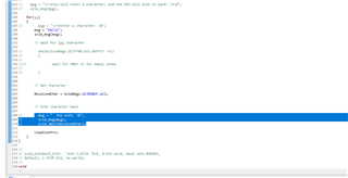
for(;;)
{
msg = "\r\nEnter a character: \0";
scia_msg(msg);
// Wait for inc character
// while(SciaRegs.SCIFFRX.bit.RXFFST !=1)
// {
// //
// // wait for XRDY =1 for empty state
// //
// }
// Get character
// ReceivedChar = SciaRegs.SCIRXBUF.all;
//
//
// // Echo character back
//
// msg = " You sent: \0";
// scia_msg(msg);
// scia_xmit(ReceivedChar);
LoopCount++;
}
}
//
// scia_echoback_init - Test 1,SCIA DLB, 8-bit word, baud rate 0x0103,
// default, 1 STOP bit, no parity
//
void
scia_echoback_init()
{
//
// Note: Clocks were turned on to the SCIA peripheral
// in the InitSysCtrl() function
//
//
// 1 stop bit, No loopback, No parity,8 char bits, async mode,
// idle-line protocol
//
SciaRegs.SCICCR.all =0x0007;
//
// enable TX, RX, internal SCICLK, Disable RX ERR, SLEEP, TXWAKE
//
SciaRegs.SCICTL1.all =0x0003;
SciaRegs.SCICTL2.bit.TXINTENA = 0;
SciaRegs.SCICTL2.bit.RXBKINTENA = 0;
//
// 9600 baud @LSPCLK = 22.5MHz (90 MHz SYSCLK)
//
SciaRegs.SCIHBAUD =0x0001;
SciaRegs.SCILBAUD =0x0024;
SciaRegs.SCICTL1.all =0x0023; // Relinquish SCI from Reset
}
//
// scia_xmit - Transmit a character from the SCI
//
void
scia_xmit(int a)
{
while (SciaRegs.SCIFFTX.bit.TXFFST != 0)
{
}
SciaRegs.SCITXBUF=a;
}
//
// scia_msg -
//
void
scia_msg(char * msg)
{
int i;
i = 0;
while(msg[i] != '\0')
{
scia_xmit(msg[i]);
i++;
}
}
//
// scia_fifo_init - Initalize the SCI FIFO
//
void
scia_fifo_init()
{
SciaRegs.SCIFFTX.all=0xE040;
SciaRegs.SCIFFRX.all=0x2044;
SciaRegs.SCIFFCT.all=0x0;
}F2806x_Sci.c: InitSciaGpio() function called in main.c
void
InitSciaGpio()
{
    EALLOW;

    //
    // Enable internal pull-up for the selected pins
    // Pull-ups can be enabled or disabled disabled by the user.
    // This will enable the pullups for the specified pins.
    //
    GpioCtrlRegs.GPAPUD.bit.GPIO28 = 0;  // Enable pull-up for GPIO28 (SCIRXDA)
    //GpioCtrlRegs.GPAPUD.bit.GPIO7 = 0;  // Enable pull-up for GPIO7 (SCIRXDA)

    GpioCtrlRegs.GPAPUD.bit.GPIO29 = 0;	 // Enable pull-up for GPIO29 (SCITXDA)
    //GpioCtrlRegs.GPAPUD.bit.GPIO12 = 0; // Enable pull-up for GPIO12 (SCITXDA)

    //
    // Set qualification for selected pins to asynch only
    // Inputs are synchronized to SYSCLKOUT by default.
    // This will select asynch (no qualification) for the selected pins.
    //
    GpioCtrlRegs.GPAQSEL2.bit.GPIO28 = 3;  // Asynch input GPIO28 (SCIRXDA)
    //GpioCtrlRegs.GPAQSEL1.bit.GPIO7 = 3;   // Asynch input GPIO7 (SCIRXDA)

    //
    // Configure SCI-A pins using GPIO regs
    // This specifies which of the possible GPIO pins will be SCI functional
    // pins.
    //

    //
    // Configure GPIO28 for SCIRXDA operation
    //
    GpioCtrlRegs.GPAMUX2.bit.GPIO28 = 1;

    //
    // Configure GPIO7  for SCIRXDA operation
    //
    //GpioCtrlRegs.GPAMUX1.bit.GPIO7 = 2;

    //
    // Configure GPIO29 for SCITXDA operation
    //
    GpioCtrlRegs.GPAMUX2.bit.GPIO29 = 1;

    //
    // Configure GPIO12 for SCITXDA operation
    //
    //GpioCtrlRegs.GPAMUX1.bit.GPIO12 = 2;

    EDIS;
}
#endif // endif DSP28_SCIA
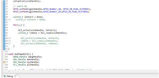
New program using the files used in proj_lab10d: I tried using SCI_putDataNonBlocking() as this was used in the motorware_hal_tutorial, and I also tried to use the SCI_write() function
main.c
#include "sw/drivers/sci/src/32b/f28x/f2806x/sci.h"
#include "sw/drivers/clk/src/32b/f28x/f2806x/clk.h"
#include "sw/drivers/gpio/src/32b/f28x/f2806x/gpio.h"
#include <inttypes.h>
#include <stdio.h>
#include <stdlib.h>
/**
 * main.c
 */

void setupSciA(SCI_Handle sciAHandle);

int main(void)
{
    SCI_Handle sciAHandle;
    CLK_Handle clkHandle;
    GPIO_Handle gpioHandle;

    sciAHandle = SCI_init((void *)SCIA_BASE_ADDR,sizeof(SCI_Obj));
    clkHandle = CLK_init((void *)CLK_BASE_ADDR,sizeof(CLK_Obj));
    gpioHandle = GPIO_init((void *)GPIO_BASE_ADDR,sizeof(GPIO_Obj));

    setupSciA(sciAHandle);
    CLK_enableSciaClock(clkHandle);

    // UARTA RX
    GPIO_setMode(gpioHandle,GPIO_Number_28, GPIO_28_Mode_SCIRXDA);
    GPIO_setMode(gpioHandle,GPIO_Number_29,GPIO_29_Mode_SCITXDA);

    for(;;) {
        SCI_write(sciAHandle, 110);
    }
}

void setupSciA(SCI_Handle sciAHandle) {

    SCI_reset(sciAHandle);
    SCI_enableTx(sciAHandle);
    SCI_enableRx(sciAHandle);

    SCI_disableParity(sciAHandle);
    SCI_setNumStopBits(sciAHandle,SCI_NumStopBits_One);
    SCI_setCharLength(sciAHandle,SCI_CharLength_8_Bits);
    SCI_setBaudRate(sciAHandle,(SCI_BaudRate_e)(0x0061));
    SCI_setPriority(sciAHandle,SCI_Priority_FreeRun);

    SCI_enable(sciAHandle);

    return;

}
Sci.c => SCI_init() function
SCI_Handle SCI_init(void *pMemory,const size_t numBytes)
{
  SCI_Handle sciHandle;


  if(numBytes < sizeof(SCI_Obj))
    return((SCI_Handle)NULL);

  // assign the handle
  sciHandle = (SCI_Handle)pMemory;

  return(sciHandle);
}
Clk.c => CLK_init() function
CLK_Handle CLK_init(void *pMemory,const size_t numBytes)
{
  CLK_Handle clkHandle;


  if(numBytes < sizeof(CLK_Obj))
    return((CLK_Handle)NULL);

  // assign the handle
  clkHandle = (CLK_Handle)pMemory;

  return(clkHandle);
}
gpio.c => GPIO_init() function
GPIO_Handle GPIO_init(void *pMemory,const size_t numBytes)
{
  GPIO_Handle gpioHandle;


  if(numBytes < sizeof(GPIO_Obj))
    {
      return((GPIO_Handle)NULL);
    }

  // assign the handle
  gpioHandle = (GPIO_Handle)pMemory;

  return(gpioHandle);
}
clk.c => CLK_enableSciaClock() function
void CLK_enableSciaClock(CLK_Handle clkHandle)
{
  CLK_Obj *clk = (CLK_Obj *)clkHandle;


  ENABLE_PROTECTED_REGISTER_WRITE_MODE;

  // set the bits
  clk->PCLKCR0 |= CLK_PCLKCR0_SCIAENCLK_BITS;

  DISABLE_PROTECTED_REGISTER_WRITE_MODE;

  return;
}
gpio.c => GPIO_setMode() function
void GPIO_setMode(GPIO_Handle gpioHandle,const GPIO_Number_e gpioNumber,const GPIO_Mode_e mode)
{
  GPIO_Obj *gpio = (GPIO_Obj *)gpioHandle;


  ENABLE_PROTECTED_REGISTER_WRITE_MODE;

  if(gpioNumber < (GPIO_GPMUX_NUMGPIOS_PER_REG * 1))
    {
      uint_least8_t lShift = gpioNumber << 1;
      uint32_t clearBits = (uint32_t)GPIO_GPMUX_CONFIG_BITS << lShift;
      uint32_t setBits = (uint32_t)mode << lShift;

      // clear the bits
      gpio->GPAMUX1 &= (~clearBits);

      // set the bits
      gpio->GPAMUX1 |= setBits;
    }
  else if(gpioNumber < (GPIO_GPMUX_NUMGPIOS_PER_REG * 2))
    {
      uint_least8_t lShift = (gpioNumber - (GPIO_GPMUX_NUMGPIOS_PER_REG * 1)) << 1;
      uint32_t clearBits = (uint32_t)GPIO_GPMUX_CONFIG_BITS << lShift;
      uint32_t setBits = (uint32_t)mode << lShift;

      // clear the bits
      gpio->GPAMUX2 &= (~clearBits);

      // set the bits
      gpio->GPAMUX2 |= setBits;
    }
  else if(gpioNumber < (GPIO_GPMUX_NUMGPIOS_PER_REG * 3))
    {
      uint_least8_t lShift = (gpioNumber - (GPIO_GPMUX_NUMGPIOS_PER_REG * 2)) << 1;
      uint32_t clearBits = (uint32_t)GPIO_GPMUX_CONFIG_BITS << lShift;
      uint32_t setBits = (uint32_t)mode << lShift;

      // clear the bits
      gpio->GPBMUX1 &= (~clearBits);

      // set the bits
      gpio->GPBMUX1 |= setBits;
    }
  else if(gpioNumber < (GPIO_GPMUX_NUMGPIOS_PER_REG * 4))
    {
      uint_least8_t lShift = (gpioNumber - (GPIO_GPMUX_NUMGPIOS_PER_REG * 3)) << 1;
      uint32_t clearBits = (uint32_t)GPIO_GPMUX_CONFIG_BITS << lShift;
      uint32_t setBits = (uint32_t)mode << lShift;

      // clear the bits
      gpio->GPBMUX2 &= (~clearBits);

      // set the bits
      gpio->GPBMUX2 |= setBits;
    }

  DISABLE_PROTECTED_REGISTER_WRITE_MODE;

  return;
}
sci.h => SCI_write() function
static inline void SCI_write(SCI_Handle sciHandle,const uint16_t data)
{
  SCI_Obj *sci = (SCI_Obj *)sciHandle;


  // write the data
  sci->SCITXBUF = data;

  return;
}
sci.h => SCI_putDataNonBlocking() function
uint16_t SCI_putDataNonBlocking(SCI_Handle sciHandle, uint16_t data)
{
  SCI_Obj *sci = (SCI_Obj *)sciHandle;

  if(SCI_txReady(sciHandle))
    {
      // write the data
      sci->SCITXBUF = data;

      return(true);
    }

  return(false);
}
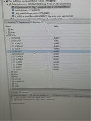
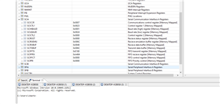
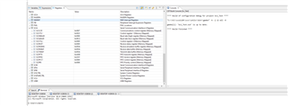
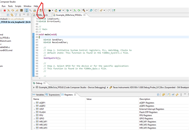
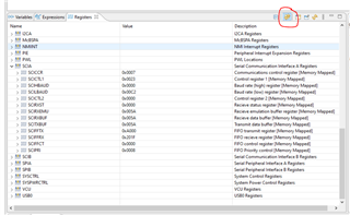
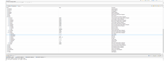
Here are the register values of each program:
ECHOBACK PROGRAM			SCI TEST PROGRAM


GPIO INIT'S

GPAPUD ->  0x00000FFF			GPAPUD ->  0x00000FFF
GPAQSEL2 -> 0x03000000			GPAQSEL2 -> 0x03000000
GPAMUX2 -> 0x05000000			GPAMUX2 -> 0x05000000

SCIA INIT'S

SCIFFTX -> 0xA000   			SCIFFTX -> 0xA000
SCIFFRX -> 0x201F			SCIFFRX -> 0x201F
SCIFFCT -> 0x0000			SCIFFCT -> 0x0000
SCICCR -> 0x0007			SCICCR -> 0x0007
SCICTL1 -> 0x0003		SCICTL1 -> 0x0023
SCICTL2 -> 0x0000		SCICTL2 -> 0x00C3
SCIHBAUD -> 0x0001			SCIHBAUD -> 0x0000 OK
SCILBAUD -> 0x0024			SCIHBAUD -> 0x00017 OK 115200
SCICTL1 -> 0x0023
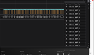
Here is the output on the logic analyzer: It just continually outputs the string "Enter a character":
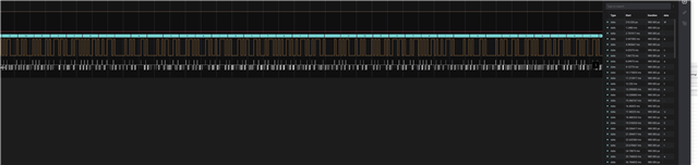

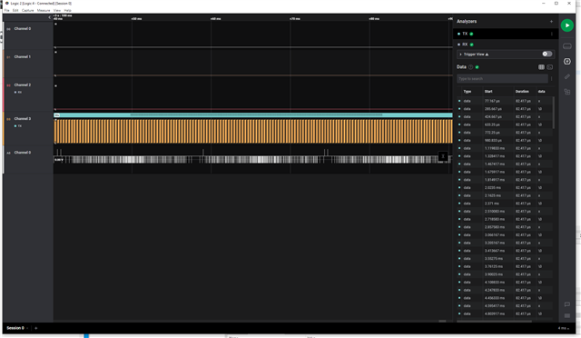
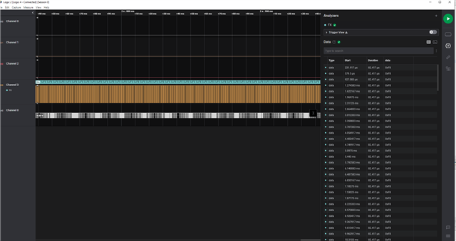
 .
.