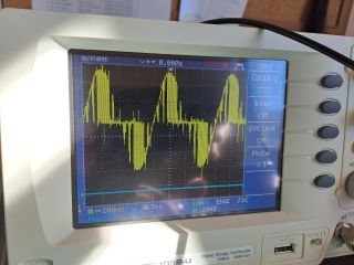
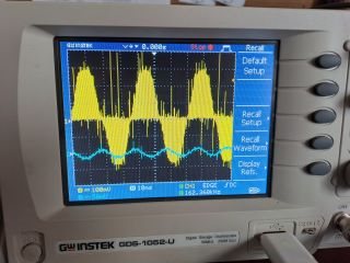
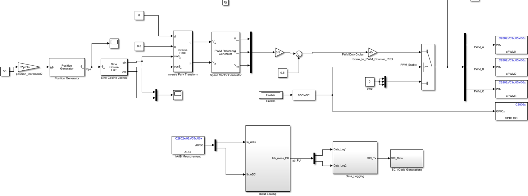
1- First, I run PMSM engine open loop with TMS320F28069M Launchpad. I used Matlab/Simulink to generate code. After converting the generally fixed reference frequency (50Hz) information into frequency information and making the necessary transformations, modulation signals were generated using the SVPWM block. And these signals were connected to the PWM blocks of the DSP. I also tried to measure current. I measured the voltage falling on the shunts by means of the shunt resistors in the N legs of the inverter circuit with an oscilloscope. Although the motor runs smoothly, gaps occur in the sine wave on the shunts (Figure 1). Afterwards, when I tried the “open loop control of 3 phase motor example, one of the samples available in Matlab/Simulink, I saw that the sine waves were normal (Figure 2). Where could this problem originate from?
2- Secondly, although the current measurement circuit offset voltage is 1.65 volts, the bit equivalent in matlab/simulink is around 1950-1960. . Shouldn't it be 0-3.3V=0-4095(2^12-1)? I think it is a value outside the tolerance limits. In my experiments by connecting potentiometers to the ADC channels, the voltage of 1.65 V corresponded to 1950-1960 bits. Is this situation normal?