This thread has been locked.

If you have a related question, please click the "Ask a related question" button in the top right corner. The newly created question will be automatically linked to this question.

TMS320F28069F: High production failure rate within F28069F models

Part Number: TMS320F28069F
Other Parts Discussed in Thread: UNIFLASH

Hello All,

We've been using various models from the F28069 DSPs especially "TMS320F28069UPFPS" and "TMS320F28069UPNT", however recently due to shortage we had to use "TMS320F28069FPNT" models that are having different ROM structures, however, we saw with them in production a major issue which is the following:

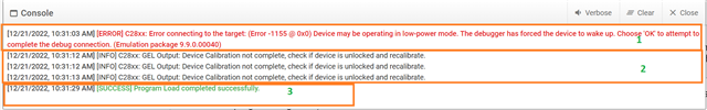
With "U" labeled DSPs we had a relatively low failure rate, meaning that in the first Flashing Attempt only less than 1% of them are failing, however in the "F" family this number is significantly higher, especially in our last production we witnessed a failure rate of 20% ( out of 400 boards, at least 80 boards) showed the following error in first flashing attempt:

[ERROR] C28xx: Flash Programmer: Error erasing flash memory. Error erasing Sector A - 65535

We have tested the flashing with our isolated XDSV100 and also separately with XDSV110 debug probe, in various boot modes, with no success, the depletion recovery also fails with the following error:

[ERROR] C28xx: Flash Programmer: Error when performing depletion recovery.

This is very concerning to us as we are ramping up our production to 100x or more and such a failure rate is not acceptable, I have to emphasize that all the failed DSPs failed in the first Erase Flash attempt, and no programming or setting of the CSM was done prior to that, so the issue with Sector A being locked is off the table ( suprisingly I can unlock the failed DSPs withing UniFlash tool)

Please let us know what should we do and how we can make sure the failure rate of these chips stays under control.

My UNIFLASH version: 7.0.0

Regards
John

  • Hi John,

    When you started using newer device, is there any change in hardware? 

    Is there any change in software or it is the same binary you are flashing?

    In the production, you are using Uniflash and you get the flash error? Does it work if you connect using CCS?

    On the failed unit, can you try 'WaitBoot' mode, does it recover?

    Regards,

    Santosh

  • Hello Santosh,

    Sorry for the delay, I've been investigating this issue further, and here's what I've found by following the below steps in my tests:

    My old way of programming the boards that were working perfectly fine for U models:

    1. The board with the new DSP and the Programmer are turned Off
    2. I turn On Both boards at the same time ( in our case the board provides power to the programmer too)
    3. The programmer fails to Flash the boards

    My new way of programming the boards that allow me to Flash the F models:

    1. The board with the new DSP and the Programmer are turned Off
    2. I turn On Both boards at the same time 
    3. I reset the DSP by connecting the XRS pin to the ground
    4. Now I can Flash the F models

    So the basic difference is now I have to manually reset the DSP after it powers up, only in that case I can flash them, so what do you think caused the issue? I didn't need to do this step with U models at all. 

    now the F models that are recovered like this are showing strange boot-up behaviors like times they don't boot up at all and the DSP remains frozen, some times they do and the code runs on them, but with F models that I can Flash them right off the bat without forcing Reset, I see no issue in Boot-up.

    Regarding your questions:

    - the software is identical, only the Linker command file is different for U and F models due to variations in ROM

    - Neither Uniflash nor CSS can't flash the boards if I don't do the Reset step

    - The hardware between the U model and F models is different only at the power stage, so the signal stages are almost identical, especially for the JTAG side and power-up routines.

    - Wait boot mode doesn't help.

    I will await your opinion.

    John

  • John,

    As 'Waitboot' did not help. We need to review the schematics. I sent you friend request. Can you please accept the request and then send the schematics through email. 

    Regards, Santosh

  • Hi John,

    After reviewing the schematics, it looks like pull-down resister for TRST line is not populated. You have DNP for TDO line also. We need to populate those registers. It is especially important on TRST line. Can you populate on the failed unit and try again?

    I discussed with my colleague. He will provide more details on power supply requirements during flash programming perspective by end of the day.

    Regards, Santosh

  • John,

    I reviewed the schematics you sent, but I need more details than what you have sent. Specifically, I need to see every/all connections to the following pins: VDD, VDDIO, -XRS, VREGNENZ, JTAG and boot-mode-select pins. Please send me a friendship request and send the schematics that show all these connections.

    The board with the new DSP and the Programmer are turned Off

    Exactly what is the "Programmer" here? I was under the impression you are using XDS100 or XDS110 debug probes.

    There are a few areas to check if flash programming fails: 

    Is the power stage able to supply the needed current during Erase/program (EP)? If the device is current-starved during E/P, that may result in a failure. However, if Erase succeeds every time and only programming fails, this is unlikely to be the reason. You could probe the power-supply pins during E/P to check if the voltage dips or if there is excessive ringing. 

    Is there any kind of interruption to the E/P process? This could potentially corrupt the password locations. 

    If you move the “faulty” device to a known-good board, does the problem follow the device?

  • Hello Hareesh,

    I've tested the faulty boards with two different programmers:

    1st programmer: XDS100-V2 ==> a custom-made insulated programmer that we made from the F28069M launchpad design( worked perfectly for thousands of units tested before this phenomenon)

    2nd programmer: XDS110 ==> standard TMDSEMU110-U.

    Is the power stage able to supply the needed current during Erase/program (EP)? If the device is current-starved during E/P, that may result in a failure. However, if Erase succeeds every time and only programming fails, this is unlikely to be the reason. You could probe the power-supply pins during E/P to check if the voltage dips or if there is excessive ringing

    On those devices that fail, The erase will also fail initially after board power-up, however, if I reset the board through the XRS pin of the DSP, I can erase the DSP ( both in normal and Boot mode as I'm programming CSM)

    Is there any kind of interruption to the E/P process? This could potentially corrupt the password locations. 

    Just using the standard Uniflash "Load Program" process to place the boot-loader, no extra step is done.

    If you move the “faulty” device to a known-good board, does the problem follow the device?

    I've tried so far to replace the faulty DSPs with new DSPs, it worked after, but still is not possible to say the issue is the DSP.

    One interesting thing with these faulty DSPs that I see in UniFlash is shown in the image below taken from Uniflash during the flashing process of a failing DSP:

    Step 1: The DSP fails to communicate with the Flash programmer ( XDS100-V2) while in boot mode and the password is correctly set in UniFlash, at this stage I have to Reset the DSP through the XRS pin.

    Step 2: at this stage, I can flash the DSP right after the reset, but I see 2 or 4 "C28xx: GEL Output: Device Calibration not complete, check if the device is unlocked and recalibrate.", this error doesn't happen on healthy DSPs.

    Step 3: The flash is programmed successfully! However, the DSPs that are flashed in this way are showing strange behaviors and they don't boot up consistently and safely, it seems sth is going wrong during flashing.

    I've monitored the 3.3V line and the voltage is consistent, I will await your friendship confirmation to share more schematics.

    John

  • This is now being handled offline.