Other Parts Discussed in Thread: TMS320F28379S, C2000WARE
Hi,
I am porting the code using the section of the lab guide for my custom baord with DrV8323rs and Tms320f28379s.
I am using different ADC pins and ports for my board as shown below.
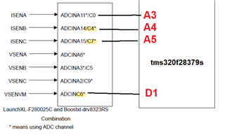
The lab source code uses ADC C for configuring the interrupts for the ADC as well as PIE since the Isense and Vmotor inputs are on the same ADC channel.
//#define MTR1_ADC_INT_BASE ADCC_BASE // ADCC-C6 -SOC
//#define MTR1_PIE_INT_NUM INT_ADCC1 // ADCC_INT1-SOC6
My motor voltage is on ADC channel D, but my Isense pins are on ADC channel A. Which ADC channel do I use for configuring interrupts, channel A or channelD.