This thread has been locked.

If you have a related question, please click the "Ask a related question" button in the top right corner. The newly created question will be automatically linked to this question.

TMS320F28069: How to verify the Period value in C2000 ware example for 2806x HR mode ?

Part Number: TMS320F28069
Other Parts Discussed in Thread: C2000WARE

Hi,

I am referring to the example at Location; C:\ti\c2000\C2000Ware_4_02_00_00\device_support\f2806x\examples\c28\hrcap_capture_hrpwm; Example_2806xHRCap_Capture_HRPwm.c 
EPWM is having 400 as a Period with SYSCLK as 60 MHz, meaning ePWM will generate a signal with a period of 6.67 Microseconds.

When I check the expression 'pulsewidthhigh' value in CCS for the same example I get the value as '17582918' which is in Q16 format, and I convert the same to uint16 and get the value as 4292. which is in the number of HCCAPCLK cycles and I convert it to seconds ( HCCAPCLK Frequency is 120 MHz in the example ), I get the High Pulse Width value as 35.76 Microseconds. 

Since the duty cycle is 50 in the example , meaning Period according to CCS should be 71.52 Micro seconds which is different from the period value generated by ePWM (6.67 Micro seconds ) 

Am I doing the wrong calculation?

  • Hi,

    Will forward this query to the EPWM expert.

    Best Regards

    Siddharth 

  • Hi Siddharth,

    Thank you for picking up the query, waiting for the response.

    Regards,

    Aditya

  • Hi Siddharth,

    Thank you for picking up the query, waiting for the response.

    Regards,

    Aditya

  • Hi Aditya,

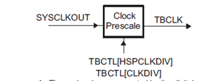
    For F28069, your epwm is clocked by TBCLK which in this case is SYSCLKOUT = 90Mhz. Since the TBPRD in the example is 400. 

    We get a period ~= 4 us half of this, is ~= 2us.

    EPwm1Regs.TBCTL.bit.HSPCLKDIV = TB_DIV1;
    EPwm1Regs.TBCTL.bit.CLKDIV = TB_DIV1;

    The HRCAP is clocked by PLL2CLK, and HCCAPCLK = 120 MHz

    //
    // In this example:
    // PLL2 = INTOSC1 (10 Mhz) * 12 / 2 = 120 MHz
    // In general, for more accuracy, source PLL2 with a crystal or
    // external clock source.
    //
    InitPll2(PLL2SRC_INTOSC1, 12, PLL2_SYSCLK2DIV2DIS);

    The high pulses are stored in Q16 format: int + fraction so we have: 17582918 (unsigned 32 bit) , or 0x010C4B46 as hex.

    The upper 16 bits contain the integer and the lower 16 bit contains the fraction denoted by the comments in the example.

    //! - pulsewidthhigh
    //! - Pulse Width of High Pulses (# of HCCAPCLK cycles - int + frac)
    //! in Q16 format (i.e. upper 16-bits integer, lower 16-bits fraction)

    Our integer we get from the above value you posted is 0x010C = 268 (decimal)

    Converting this decimal to find out our pulse width period can be done by this

    268 * (1 / (120 * 10^6)) = ~= 2 us

    And this is what we expect for the duty cycle to be 50%.