Other Parts Discussed in Thread: C2000WARE
Hi ,
The lab example uses a PWM time period number macro, which I believe is for a 100Mhz system clock using the LAUNCHXL-F280025C.
#define USER_M1_PWM_TBPRD_NUM (uint16_t)(USER_SYSTEM_FREQ_MHz * 1000.0f / USER_M1_PWM_FREQ_kHz / 2.0f)
This macro is being used by HAL_setupPWMs() for setting the pwmPeriodCycles.
uint16_t pwmPeriodCycles = (uint16_t)(USER_M1_PWM_TBPRD_NUM);
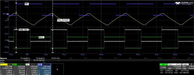
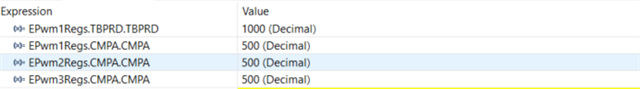
I plan to run at 50KHz PWM with a system clock of 200MHz on my custom board. What is the recommended value for this macro for a 200MHz system clock? I have tried a few combinations. For example, if I divide by 4 in the macro, to compensate for doubling the sys clock, then my PWM out is 50 KHz, but the example did not run. The TBPRD was 1000, and CMPA was 500.
If I try to set TBPRD as 2500 and CMPA as 1250 (divided by 1.6) then my output PWM is 20KHz, against the target PWM of 50Khz.
void HAL_setupPWMs(HAL_MTR_Handle handle)
{
    HAL_MTR_Obj    *obj = (HAL_MTR_Obj *)handle;
    uint16_t  cnt;

    uint16_t       pwmPeriodCycles = (uint16_t)(USER_M1_PWM_TBPRD_NUM);
    uint16_t       numPWMTicksPerISRTick = USER_M1_NUM_PWM_TICKS_PER_ISR_TICK;

    // disable the ePWM module time base clock sync signal
    // to synchronize all of the PWMs
    SysCtl_disablePeripheral(SYSCTL_PERIPH_CLK_TBCLKSYNC);

    // turns off the outputs of the EPWM peripherals which will put the power
    // switches into a high impedance state.
    EPWM_forceTripZoneEvent(obj->pwmHandle[0], EPWM_TZ_FORCE_EVENT_OST);
    EPWM_forceTripZoneEvent(obj->pwmHandle[1], EPWM_TZ_FORCE_EVENT_OST);
    EPWM_forceTripZoneEvent(obj->pwmHandle[2], EPWM_TZ_FORCE_EVENT_OST);

#if defined(BSXL8323RS_REVA) || defined(BSXL8323RH_REVB) || \
    defined(BSXL8353RS_REVA) || defined(BSXL8316RT_REVA) || \
    defined(BSXL3PHGAN_REVA) || defined(HVMTRPFC_REV1P1) || \
    defined(DRV8329AEVM_REVA)

    for(cnt=0; cnt<3; cnt++)
    {
        // setup the Time-Base Control Register (TBCTL)
        EPWM_setTimeBaseCounterMode(obj->pwmHandle[cnt],
                                    EPWM_COUNTER_MODE_UP_DOWN);

        EPWM_disablePhaseShiftLoad(obj->pwmHandle[cnt]);

        EPWM_setPeriodLoadMode(obj->pwmHandle[cnt], EPWM_PERIOD_DIRECT_LOAD);
/* Commented JS
        EPWM_enableSyncOutPulseSource(obj->pwmHandle[cnt],
                                      EPWM_SYNC_OUT_PULSE_ON_SOFTWARE);
*/
        EPWM_setClockPrescaler(obj->pwmHandle[cnt], EPWM_CLOCK_DIVIDER_2,
                                 EPWM_HSCLOCK_DIVIDER_2);

        EPWM_setCountModeAfterSync(obj->pwmHandle[cnt],
                                   EPWM_COUNT_MODE_UP_AFTER_SYNC);

        EPWM_setEmulationMode(obj->pwmHandle[cnt], EPWM_EMULATION_FREE_RUN);

        // setup the Timer-Based Phase Register (TBPHS)
        EPWM_setPhaseShift(obj->pwmHandle[cnt], 0);

        // setup the Time-Base Counter Register (TBCTR)
        EPWM_setTimeBaseCounter(obj->pwmHandle[cnt], 0);

        // setup the Time-Base Period Register (TBPRD)
        // set to zero initially
        EPWM_setTimeBasePeriod(obj->pwmHandle[cnt], 0);

        // setup the Counter-Compare Control Register (CMPCTL)
        EPWM_setCounterCompareShadowLoadMode(obj->pwmHandle[cnt],
                                             EPWM_COUNTER_COMPARE_A,
                                             EPWM_COMP_LOAD_ON_CNTR_ZERO);

        EPWM_setCounterCompareShadowLoadMode(obj->pwmHandle[cnt],
                                             EPWM_COUNTER_COMPARE_B,
                                             EPWM_COMP_LOAD_ON_CNTR_ZERO);

        EPWM_setCounterCompareShadowLoadMode(obj->pwmHandle[cnt],
                                             EPWM_COUNTER_COMPARE_C,
                                             EPWM_COMP_LOAD_ON_CNTR_ZERO);

        EPWM_setCounterCompareShadowLoadMode(obj->pwmHandle[cnt],
                                             EPWM_COUNTER_COMPARE_D,
                                             EPWM_COMP_LOAD_ON_CNTR_ZERO);

#if defined(MOTOR1_ISBLDC)
        // setup the Action-Qualifier Output A Register (AQCTLA)
        EPWM_setActionQualifierAction(obj->pwmHandle[cnt],
                                      EPWM_AQ_OUTPUT_A,
                                      EPWM_AQ_OUTPUT_HIGH,
                                      EPWM_AQ_OUTPUT_ON_TIMEBASE_UP_CMPA);

        EPWM_setActionQualifierAction(obj->pwmHandle[cnt],
                                      EPWM_AQ_OUTPUT_A,
                                      EPWM_AQ_OUTPUT_LOW,
                                      EPWM_AQ_OUTPUT_ON_TIMEBASE_DOWN_CMPA);

        // setup the Action-qualifier Continuous Software Force Register (AQCSFRC)
        EPWM_setActionQualifierContSWForceAction(obj->pwmHandle[cnt],
                                                 EPWM_AQ_OUTPUT_B,
                                                 EPWM_AQ_SW_OUTPUT_LOW);

        // setup the Dead-Band Generator Control Register (DBCTL)
        EPWM_setDeadBandDelayMode(obj->pwmHandle[cnt], EPWM_DB_RED, false);
        EPWM_setDeadBandDelayMode(obj->pwmHandle[cnt], EPWM_DB_FED, false);

#else   //!MOTOR1_ISBLDC


#if defined(MOTOR1_DCLINKSS)
        // setup the Action-Qualifier Output A Register (AQCTLA)
        EPWM_setActionQualifierAction(obj->pwmHandle[cnt],
                                      EPWM_AQ_OUTPUT_A,
                                      EPWM_AQ_OUTPUT_HIGH,
                                      EPWM_AQ_OUTPUT_ON_TIMEBASE_UP_CMPA);

        EPWM_setActionQualifierAction(obj->pwmHandle[cnt],
                                      EPWM_AQ_OUTPUT_A,
                                      EPWM_AQ_OUTPUT_LOW,
                                      EPWM_AQ_OUTPUT_ON_TIMEBASE_DOWN_CMPB);

        EPWM_setActionQualifierAction(obj->pwmHandle[cnt],
                                      EPWM_AQ_OUTPUT_A,
                                      EPWM_AQ_OUTPUT_LOW,
                                      EPWM_AQ_OUTPUT_ON_TIMEBASE_ZERO);

        EPWM_setActionQualifierAction(obj->pwmHandle[cnt],
                                      EPWM_AQ_OUTPUT_A,
                                      EPWM_AQ_OUTPUT_HIGH,
                                      EPWM_AQ_OUTPUT_ON_TIMEBASE_PERIOD);
#else  // !(MOTOR1_DCLINKSS)
        // setup the Action-Qualifier Output A Register (AQCTLA)
        EPWM_setActionQualifierAction(obj->pwmHandle[cnt],
                                      EPWM_AQ_OUTPUT_A,
                                      EPWM_AQ_OUTPUT_HIGH,
                                      EPWM_AQ_OUTPUT_ON_TIMEBASE_UP_CMPA);

        EPWM_setActionQualifierAction(obj->pwmHandle[cnt],
                                      EPWM_AQ_OUTPUT_A,
                                      EPWM_AQ_OUTPUT_HIGH,
                                      EPWM_AQ_OUTPUT_ON_TIMEBASE_PERIOD);

        EPWM_setActionQualifierAction(obj->pwmHandle[cnt],
                                      EPWM_AQ_OUTPUT_A,
                                      EPWM_AQ_OUTPUT_LOW,
                                      EPWM_AQ_OUTPUT_ON_TIMEBASE_DOWN_CMPA);

        EPWM_setActionQualifierAction(obj->pwmHandle[cnt],
                                      EPWM_AQ_OUTPUT_A,
                                      EPWM_AQ_OUTPUT_LOW,
                                      EPWM_AQ_OUTPUT_ON_TIMEBASE_ZERO);

#endif  // !(MOTOR1_DCLINKSS)

        // setup the Dead-Band Generator Control Register (DBCTL)
        EPWM_setDeadBandDelayMode(obj->pwmHandle[cnt], EPWM_DB_RED, true);
        EPWM_setDeadBandDelayMode(obj->pwmHandle[cnt], EPWM_DB_FED, true);

        // select EPWMA as the input to the dead band generator
        EPWM_setRisingEdgeDeadBandDelayInput(obj->pwmHandle[cnt],
                                             EPWM_DB_INPUT_EPWMA);

        // configure the right polarity for active high complementary config.
        EPWM_setDeadBandDelayPolarity(obj->pwmHandle[cnt],
                                      EPWM_DB_RED,
                                      EPWM_DB_POLARITY_ACTIVE_HIGH);
        EPWM_setDeadBandDelayPolarity(obj->pwmHandle[cnt],
                                      EPWM_DB_FED,
                                      EPWM_DB_POLARITY_ACTIVE_LOW);

        // setup the Dead-Band Rising Edge Delay Register (DBRED)
        EPWM_setRisingEdgeDelayCount(obj->pwmHandle[cnt], MTR1_PWM_DBRED_CNT);

        // setup the Dead-Band Falling Edge Delay Register (DBFED)
        EPWM_setFallingEdgeDelayCount(obj->pwmHandle[cnt], MTR1_PWM_DBFED_CNT);

#endif  //!MOTOR1_ISBLDC

        // setup the PWM-Chopper Control Register (PCCTL)
        EPWM_disableChopper(obj->pwmHandle[cnt]);

        // setup the Trip Zone Select Register (TZSEL)
        EPWM_disableTripZoneSignals(obj->pwmHandle[cnt], HAL_TZSEL_SIGNALS_ALL);
    }

    // BSXL8323RS_REVA || BSXL8323RH_REVB || BSXL8353RS_REVA || \
    // BSXL8316RT_REVA || BSXL3PHGAN_REVA || HVMTRPFC_REV1P1 || \
    // DRV8329AEVM_REVA
#else
#error The PWM is not configured for motor_1 control
#endif  // boards

#if defined(MOTOR1_ISBLDC)
    // setup the Event Trigger Selection Register (ETSEL)
    EPWM_setInterruptSource(obj->pwmHandle[0], EPWM_INT_TBCTR_ZERO);

    EPWM_disableInterrupt(obj->pwmHandle[0]);

    EPWM_setADCTriggerSource(obj->pwmHandle[0],
                             EPWM_SOC_A, EPWM_SOC_TBCTR_ZERO);

    EPWM_enableADCTrigger(obj->pwmHandle[0], EPWM_SOC_A);

    EPWM_setADCTriggerSource(obj->pwmHandle[0],
                              EPWM_SOC_B, EPWM_SOC_TBCTR_U_CMPB);

    EPWM_enableADCTrigger(obj->pwmHandle[0], EPWM_SOC_B);
#elif defined(MOTOR1_DCLINKSS)
    // setup the Event Trigger Selection Register (ETSEL)
    EPWM_setInterruptSource(obj->pwmHandle[0], EPWM_INT_TBCTR_ZERO);

    EPWM_enableInterrupt(obj->pwmHandle[0]);

    EPWM_setADCTriggerSource(obj->pwmHandle[0],
                             EPWM_SOC_A, EPWM_SOC_TBCTR_D_CMPC);

    EPWM_enableADCTrigger(obj->pwmHandle[0], EPWM_SOC_A);

    // ADC SOC trigger for the 1st dc-link current sampling
    EPWM_setADCTriggerSource(obj->pwmHandle[1],
                                 EPWM_SOC_A,
                                 EPWM_SOC_TBCTR_U_CMPC);

    EPWM_enableADCTrigger(obj->pwmHandle[1], EPWM_SOC_A);

    // ADC SOC trigger for the 2nd dc-link current sampling
    EPWM_setADCTriggerSource(obj->pwmHandle[1],
                             EPWM_SOC_B,
                             EPWM_SOC_TBCTR_U_CMPD);

    EPWM_enableADCTrigger(obj->pwmHandle[1], EPWM_SOC_B);

    // ADC SOC trigger for the 3rd dc-link current sampling
    EPWM_setADCTriggerSource(obj->pwmHandle[2],
                                 EPWM_SOC_A,
                                 EPWM_SOC_TBCTR_D_CMPC);

    EPWM_enableADCTrigger(obj->pwmHandle[2], EPWM_SOC_A);

    // ADC SOC trigger for the 4th dc-link current sampling
    EPWM_setADCTriggerSource(obj->pwmHandle[2],
                             EPWM_SOC_B,
                             EPWM_SOC_TBCTR_D_CMPD);

    EPWM_enableADCTrigger(obj->pwmHandle[2], EPWM_SOC_B);
#else   //!(MOTOR1_ISBLDC || MOTOR1_DCLINKSS)
    // setup the Event Trigger Selection Register (ETSEL)
    EPWM_setInterruptSource(obj->pwmHandle[0], EPWM_INT_TBCTR_ZERO);

    EPWM_enableInterrupt(obj->pwmHandle[0]);

    EPWM_setADCTriggerSource(obj->pwmHandle[0],
                             EPWM_SOC_A, EPWM_SOC_TBCTR_D_CMPC);

    EPWM_enableADCTrigger(obj->pwmHandle[0], EPWM_SOC_A);
#endif  // !(MOTOR1_ISBLDC || MOTOR1_DCLINKSS)

    // setup the Event Trigger Prescale Register (ETPS)
    if(numPWMTicksPerISRTick > 15)
    {
        numPWMTicksPerISRTick = 15;
    }
    else if(numPWMTicksPerISRTick < 1)
    {
        numPWMTicksPerISRTick = 1;
    }

    EPWM_setInterruptEventCount(obj->pwmHandle[0], numPWMTicksPerISRTick);

    EPWM_setADCTriggerEventPrescale(obj->pwmHandle[0], EPWM_SOC_A,
                                    numPWMTicksPerISRTick);
    EPWM_setADCTriggerEventPrescale(obj->pwmHandle[0], EPWM_SOC_B,
                                    numPWMTicksPerISRTick);

#if defined(MOTOR1_DCLINKSS)
    EPWM_setADCTriggerEventPrescale(obj->pwmHandle[1], EPWM_SOC_A,
                                    numPWMTicksPerISRTick);
    EPWM_setADCTriggerEventPrescale(obj->pwmHandle[1], EPWM_SOC_B,
                                    numPWMTicksPerISRTick);

    EPWM_setADCTriggerEventPrescale(obj->pwmHandle[2], EPWM_SOC_A,
                                    numPWMTicksPerISRTick);
    EPWM_setADCTriggerEventPrescale(obj->pwmHandle[2], EPWM_SOC_B,
                                    numPWMTicksPerISRTick);
#endif  //MOTOR1_DCLINKSS

    // setup the Event Trigger Clear Register (ETCLR)
    EPWM_clearEventTriggerInterruptFlag(obj->pwmHandle[0]);
    EPWM_clearADCTriggerFlag(obj->pwmHandle[0], EPWM_SOC_A);
    EPWM_clearADCTriggerFlag(obj->pwmHandle[0], EPWM_SOC_B);

    // since the PWM is configured as an up/down counter, the period register is
    // set to one-half of the desired PWM period
    EPWM_setTimeBasePeriod(obj->pwmHandle[0], pwmPeriodCycles);
    EPWM_setTimeBasePeriod(obj->pwmHandle[1], pwmPeriodCycles);
    EPWM_setTimeBasePeriod(obj->pwmHandle[2], pwmPeriodCycles);

    // write the PWM data value  for ADC trigger
    EPWM_setCounterCompareValue(obj->pwmHandle[0], EPWM_COUNTER_COMPARE_C, 10);

    // write the PWM data value  for ADC trigger
#if defined(MOTOR1_DCLINKSS)
    EPWM_clearADCTriggerFlag(obj->pwmHandle[1], EPWM_SOC_A);
    EPWM_clearADCTriggerFlag(obj->pwmHandle[1], EPWM_SOC_B);

    EPWM_clearADCTriggerFlag(obj->pwmHandle[2], EPWM_SOC_A);
    EPWM_clearADCTriggerFlag(obj->pwmHandle[2], EPWM_SOC_B);

    EPWM_setCounterCompareValue(obj->pwmHandle[1],
                                EPWM_COUNTER_COMPARE_C, pwmPeriodCycles>>1);
    EPWM_setCounterCompareValue(obj->pwmHandle[1],
                                EPWM_COUNTER_COMPARE_D, pwmPeriodCycles>>1);

    EPWM_setCounterCompareValue(obj->pwmHandle[2],
                                EPWM_COUNTER_COMPARE_C, pwmPeriodCycles>>1);
    EPWM_setCounterCompareValue(obj->pwmHandle[2],
                                EPWM_COUNTER_COMPARE_D, pwmPeriodCycles>>1);

#endif  //MOTOR1_DCLINKSS


    // enable the ePWM module time base clock sync signal
    SysCtl_enablePeripheral(SYSCTL_PERIPH_CLK_TBCLKSYNC);

    return;
}  // end of HAL_setupPWMs() function