This thread has been locked.

If you have a related question, please click the "Ask a related question" button in the top right corner. The newly created question will be automatically linked to this question.

PMP23126: SYNCPER signal configuration

Part Number: PMP23126
Other Parts Discussed in Thread: TIDM-02000

Hi,

I'm investigating the PMP23126 document. My questions are related to inner loop of PCMC with no SR case.

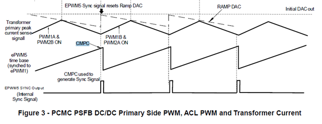
1) In figure 3 as below, CMPC signal is used as to generate SYNCPER signal. Could you please explain why designer choose CMPC instead of ZERO or PERIOD? EPWM5 can be easily sync to ePWM1 with setting 2 as phase shift on epwm5. It is then fully sync to ePWM1 and SYNCPER signal can be easily created at when TBCTR=ZERO. Could you please comment on it?

a) How do you decide the CMPC value? Is there any phase offset in the configuration of time-base counter for ePWM5 comparing to ePMW1. I didn't see related lines in software. Please, download from resource explorer?

b) Is CMPC equal to Period + dead-band of ePWM1B? It doesn't seem very well in the figure 3.

c) Do you update the value of CMPC when dead-band of ePWM1B is changed?

d) I downloaded the example code for PMP23126, however, I didn't see related lines to use EPWM5 and SYNCPER to sync for CMPSS module? Could you please show me where those lines?

e) Is there any delay time caused by SYNCPER signal to be monitored and qualified on CMPSS module?

f) What is the duty cycle range with event based phase shifting operation? Can I get %100 or %0 duty cycle? I also asked this question for TIDM-02000.

2) How do you decide the value of blanking window length and its offset? I think if I change the deadband in ePWM1, I should also update the window lenght? If yes, Could you please show me where those lines are written in software? I didn't see those lines in software. I can download new one if you guide me.

3) If I set 0 to the RAMPMAX to the internal DAC of CMPSS, is its output zero also in volts? Is there any minimum value when 0 is loaded?

Thanks in advance.

  • Hi Gokhan,

    1. This design uses peak current mode control and the peak-current compare is done in both halves of the switching cycle. Yes, it is true you can use the time-base counter to easily achieve phase shift between ePWM1 and ePWM2 but this is more akin to voltage mode control for PSFB and in this case you would need DC blocking cap to avoid the transformer eventually walking away into saturation. 

    2. Because this design uses active clamp, there is a minimum duty cycle that needs to be maintained in order to avoid turning on the active clamps during the free-wheeling period of the switching cycle. This blanking window was set to ensure this minimum time. The blanking window should be longer than your dead time. In the code, C2000 updates the primary side dead time based on the load current. You can find the dead-time adjustment code in psfbpcmc.h.

    3. RAMPMAX refers to the starting value of the slope compensation added to the turn-off threshold. a value of 0 would mean no slope compensation and it will likely result in sub-harmonic oscillation if the effective duty cycle is >50%. 

    Best Regards,

    Ben Lough

  • Hi Benjamin, Thank you for answers.

    Could you please re-investigate my questions in details? I couldn't get what I needed.

    1. This design uses peak current mode control and the peak-current compare is done in both halves of the switching cycle. Yes, it is true you can use the time-base counter to easily achieve phase shift between ePWM1 and ePWM2 but this is more akin to voltage mode control for PSFB and in this case you would need DC blocking cap to avoid the transformer eventually walking away into saturation. 

    Yes, I got it. However, my questions isn't related to it. It is why you didn't choose ePWM5 with fully snyc to ePWM1. You set CMPC, but, why not TBCTR=zero or period. You could get ePWM5 fully sync to ePMW1.

    2. Because this design uses active clamp, there is a minimum duty cycle that needs to be maintained in order to avoid turning on the active clamps during the free-wheeling period of the switching cycle. This blanking window was set to ensure this minimum time. The blanking window should be longer than your dead time. In the code, C2000 updates the primary side dead time based on the load current. You can find the dead-time adjustment code in psfbpcmc.h
    This blanking window was set to ensure this minimum time

    What is the minimum duty cycle value? Could you please guide me with calculations? 

    In the code, C2000 updates the primary side dead time based on the load current.

    But you don't update the blanking window in the code or the CMPC value. Do you update?

    RAMPMAX refers to the starting value of the slope compensation added to the turn-off threshold. a value of 0 would mean no slope compensation and it will likely result in sub-harmonic oscillation if the effective duty cycle is >50%. 

    My question is related to internal DAC characteristics. Is there any offset in CMPSS comparator.

    Thank you in advance.

  • Hi,

    Could you please help me on this issue?

  • Hi Gokhan,

    1. From software perspective, yes. TBCTR=PERIOD would be similar to using CMPC value

    2. There is an initial delay from the moment a diagonal pair of primary side FETs turn on to the rising edge of the active clamp pulse. This delay is set in psfbpcmc_user_settings.h at PSFB_ACL_DEADBAND_RED_INITIAL. For 28004x device with 100Mhz clock, a value of 70 is 70/(100MHz) = 700ns. In psfbpcmc_hal.c, the ACL time is set by EPWM CounterCompareValue. For a value of 100, this gives 100-70/(100MHz) = 300ns pulse width for the active clamp. This active clamp pulse is active twice every switching cycle. The minimum duty cycle you therefore can have is 2*1us/(1/100kHz) = 0.2. 

    3. No blanking window is not updated.

    4. In the code, there is a minimum value set for iref which is translated to a DAC value to CMPSS. This would limit the minimum value for the DAC. 

    Best Regards,

    Ben Lough

  • Hi Benjamin,

    Thank you for detailed explanation. I really  appreciated. Could you please help on followings?

    4. In the code, there is a minimum value set for iref which is translated to a DAC value to CMPSS. This would limit the minimum value for the DAC.

    I think it is 0. It is set by PSFB_irampmax_Set. Therefore, 0 may not mean 0 at internal CMPSS DAC output? Could you please comment?

    1.1) How do you decide the CMPC value? Is there any phase offset in the configuration of time-base counter for ePWM5 comparing to ePMW1. I didn't see related lines in software.

    1.2) Is CMPC equal to Period + dead-band of ePWM1B? It doesn't seem very well in the figure 3.

    1.3) Do you update the value of CMPC when dead-band of ePWM1B is changed?

    1.4) I downloaded the example code for PMP23126, however, I didn't see related lines to use EPWM5 and SYNCPER to sync for CMPSS module? Could you please show me where those lines?

    1.5) Is there any delay time caused by SYNCPER signal to be monitored and qualified on CMPSS module?

    New Question) I couldn't find the transformer datasheet, which has part number PAT6561NL, that is shown in Test Report: PMP23126.

  • Hi Gokhan,

    Below is the transformer datasheet:

    /cfs-file/__key/communityserver-discussions-components-files/171/PAT6561NL-MX2.pdf

    May I ask what are you attempting to do or change in the code? Is there some special use case you are attempting to address in your application that is outside of what PMP23126 accomplishes?

    Best Regards,

    Ben Lough

  • Hi Benjamin,

    I'm trying to design software of my board, which is PSFB CDR topology. I'm using F280048. I'm investigating the example software and trying the understand the features of C2000 and how to use them safely.

    Could you please help me about questions?

  • Hi Gokhan,

    No, the Iref min is 0.13. It is defined in psfbpcmc_settings.h. Iref and Iramp are not the same thing. In psfbpcmc.h, PSFB_irampmax_Set = PSFB_icommand_Set_pu * PSFB_IRAMPMAX_SET_RATIO. The ratio is set in psfbpcmc_user_settings.h and is 65534. So if the minimum value of icommand is 0.13, then the minimum value is 8519.

    You can refer to psfbpcmc_hal.c and psfbpcmc_hal.h. A lot of the EPWM setup is implemented there.

    1. No phase shift between EPWM1 and EPWM5.

    2. It should be equal to the pulse width of EPWM1B + the deadtime

    3. No.

    4. take a look at psfbpcmc_hal.c and psfbpcmc_hal.h

    5. I would refer to the CMPSS documentation if you are worried about comparator delay times causing issues in your design. 

    https://www.ti.com/lit/ug/sprui33f/sprui33f.pdf?ts=1678301863488&ref_url=https%253A%252F%252Fwww.ti.com%252Fproduct%252FTMS320F280049C

    Best Regards,

    Ben Lough

  • Thanks Benjamin, You helped me a lot. 

  • Hi Benjamin,

    One more question;

    1) Why did you set timebase counter to 2?

    2) Why did you set phase shift as 2?

    3) Why did you set CMPC to period -5?

    CMPC value is constant, I think you don't update it in other lines depending on the deadband value at ePWM1.

    void PSFB_HAL_setupAdcOvrSamplPWM(uint32_t base1, uint16_t pwm_period_ticks)
    {
        EALLOW;
        EPWM_setPeriodLoadMode(base1, EPWM_PERIOD_DIRECT_LOAD);
        EPWM_setTimeBasePeriod(base1, pwm_period_ticks - 1);
        EPWM_setTimeBaseCounter(base1, 2);
        EPWM_setPhaseShift(base1, 2);
        EPWM_setTimeBaseCounterMode(base1, EPWM_COUNTER_MODE_UP);
        EPWM_setClockPrescaler(base1, EPWM_CLOCK_DIVIDER_1, EPWM_HSCLOCK_DIVIDER_1);     EPWM_enablePhaseShiftLoad(base1);     HRPWM_setSyncPulseSource(base1, HRPWM_PWMSYNC_SOURCE_COMPC_UP);
        EPWM_setCounterCompareValue(base1, EPWM_COUNTER_COMPARE_C,
                                     pwm_period_ticks - 5);     
                                     EDIS;
    }


  • Hello Gokhan,

    Answers to your remaining questions:

    1) Why did you set timebase counter to 2?

    Likely just a copy-paste error. However, it shouldn't make a difference since the PWM counter will be synchronized to PWM1.

    2) Why did you set phase shift as 2?

    Likely just a copy-paste error. However, it shouldn't matter since the phase shift is not enabled for this PWM.

    3) Why did you set CMPC to period -5?

    Using CMPC as the SYNCPER signal gives you some flexibility to trip the CMPSS some cycles before the CTR=PRD. Setting CMPC = pwm_period_ticks - 5 is just leveraging that flexibility.

    CMPC value is constant, I think you don't update it in other lines depending on the deadband value at ePWM1.

    Correct, CMPC value always remains constant. The PWM1 deadband configuration does not depend on CMPC at all. CMPC is there only to trigger the CMPSS.

  • Hello Gus,

    Likely just a copy-paste error. However, it shouldn't matter since the phase shift is not enabled for this PWM.

    I saw that "EPWM_enablePhaseShiftLoad(base1);" is used for PSFB_HAL_setupAdcOvrSamplPWM. Therefore, I cannot understand.

    Using CMPC as the SYNCPER signal gives you some flexibility to trip the CMPSS some cycles before the CTR=PRD. Setting CMPC = pwm_period_ticks - 5 is just leveraging that flexibility

    Yes. I though that it would be easy to generate SYNCPER at CTR=PRD or CTR=ZERO. If there is any tricks, I wondered to learn it. Everything seemed to me not just an error.

    Thank you.