


Hi Team,
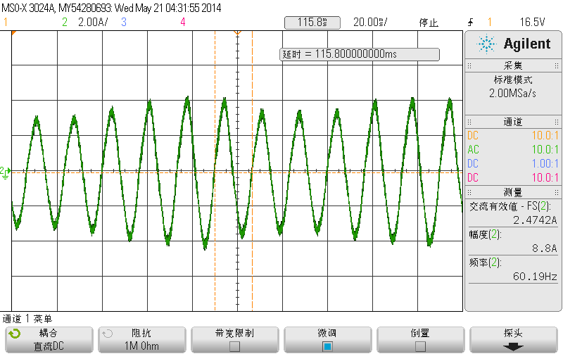
1.负载200欧的时候,输入相电压120V,输出直流电压400V,建立BUILD2电流环,ilref=0.2,时,测的相电流波形如图所示,无法达到参考电压400V,请问电流波动的原因?
2.测试过程中出现过流保护,,是什么原因造成的。
1. When the load is 200 ohms, the input phase voltage is 120V, and the output DC voltage is 400V. When the BUILD2 current loop is established, ilref=0.2, the measured phase current waveform is as shown in the picture, and the reference voltage cannot reach 400V. What is the reason for the current fluctuation?
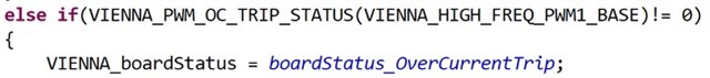
2. Overcurrent protection occurs during the test, and what is the reason for this?
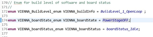
3. Can the powerstageoff in line 174 be changed to powerstageon? What is the function of this line?
Kind regards,
Katherine


