This thread has been locked.

If you have a related question, please click the "Ask a related question" button in the top right corner. The newly created question will be automatically linked to this question.

TMS320F28379D: TMS320F28379D microcontroller output source current and output sink current effect on reliability

Part Number: TMS320F28379D
Other Parts Discussed in Thread: UCC5310

Dear TI team,

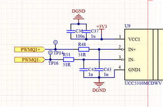
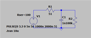
We're using TMS320F28379DPTPT (HLQFP package). ePWM pin (100 kHz frequency) is input to gate driver which has RC filter (50 ohms and 1 nF). In this case current being sourced and withdrawn from MCU pin requirement is very high compared to the capabilities given in the datasheet (-4/+4 mA).

    1. Does this affect the reliability of MCU in long term?

    2. Does drawing current for long from multiple pins affect the operation of other pins? We're using 8 such ePWM pins for DAB converter and many other IOs for other purposes.

Let me know if you've any questions.

  • Jitendra,

              What is on the “other end” of the RC filter? The input to the gate-driver should have high-impedance, correct? Just trying to understand how you concluded that your design will be exceeding the rated buffer output current. If it is OK with you, you can share the schematics of the PWM output stage. If you don’t want to post it on the forum, you can send me a private message by initiating a friendship request.

    1. Does this affect the reliability of MCU in long term?

    If you exceed the rated current, it would indeed  affect the long term reliability of the MCU.

      2. Does drawing current for long from multiple pins affect the operation of other pins? We're using 8 such ePWM pins for DAB converter and many other IOs for other purposes.

    The mere usage of multiple I/O pins, in itself, is no reason for concern. It will not affect the operation of other pins. The device is designed to be used this way. 

  • Dear Hareesh, Thanks.

    Yes, input of gate driver is high impedance. Below is the snapshot of input stage:

    Signal PWMQ1+ is coming directly from microcontroller.

    I tried this simple thing in simulator. Below are the screenshots

    100 ohm is added in series with source to limit the current. Either MCU current will overshoot or it will limit the current for long.

    There are 8 such gate drivers in the design. So continuously ePWM pins are loaded.

    Do we need to change the configuration or it looks ok?

    Regards,

    Jitendra

  • Jitendra,

    The 4mA rating for these pins is the DC rating, some overshoot of this current is expected when switching.  However, driving a large capacitor frequently like this can result in an RMS effective current that could affect reliability; you are asking the right question.  I would calculate the RMS current based on the highest frequency you expect and target that to be below 4mA.

    In general, I would steer you away from putting an RC filter like this on signal pins.  It slows down the transition, so the signal spends more time in the 'no mans land' between Vih/Vil.  When in this region if there is a noise event larger than the Hysteresis value of the input buffer it could cause a glitch to propagate.  Sharper edges will have less opportunity for this.  Of course, the RC should reduce noise events, but it really just depends on where the noise occurs.  

    Overall I'd suggest reducing this RC filter size (if not removing it) and require tight placement of the RC next to the receiver UCC5310 device.

    Best regards,

    Jason

  • Thanks. Frequency of operation is 100 kHz with 50% duty cycle. It is more clear now.

  • Jitendra, glad this helps, thanks for the reply.

    Looking back at the waveform again I see it crosses 20mA.  This is the Absolute Maximum rating for the output buffers.  Since this is continuous, it would probably be good to further limit this spike.  Maybe a 100ohm resistor and/or slightly smaller capacitor would be good to limit the peak current.

    Best regards,

    Jason